Microfabricated crossflow devices and methods

Inactive Publication Date: 2007-11-13
CALIFORNIA INST OF TECH
View PDF122 Cites 491 Cited by
  • Summary
  • Abstract
  • Description
  • Claims
  • Application Information

AI Technical Summary

Benefits of technology

[0014]The microfabricated device and methods of the invention offer several advantages over traditional flow cytometry devices and methods. Since the channels present in the device can be made with micron dimensions, the volume of the detection region is precisely controlled and there is no need for hydrodynamic focusing. The planar geometry of the device allows the use of high numerical aperture optics, thereby increasing the sensitivity of the system. Fluid flows continuously through the system and there is no need for charged droplets, so that many difficult technical issues associated with traditional, e. g., FACS devices are avoided. Because the system is entirely self-contained, there is no aerosol formation's, allowing for much safer sorting of biohazardous materials such as viruses and other pathogens. Also, the so

Problems solved by technology

Therefore, they cannot be grown in synthetic culture media like many other pathogens.
However, this sensitivity of detection can also cause significant problems in routine viral diagnostics.
The significant risk of cross-contamination from sample to sample can outweigh the benefits of detecting small quantities of a target viral nucleic acid.
Cross-contamination can also result in false positives, making interpretation of epidemiological data impossible.
Conventional flow sorters, such as FACS have numerous problems that render them impractical for analyzing and sorting viruses and other similarly sized particles.
Despite these advances, many failures of these instruments are due to problems in the flow chamber.
For example, orifice clogging, particle absorption and contamination in the tubing may cause turbulent flow in the jet stream.
These problems contribute to the great variation in illumination and detection in conventional FACS devices.
Another major problem, known as sample carryover, occurs when remnants of previous specimens left in the channel back-flush into the new sample stream during consecutive runs.
A potentially more serious problem occurs when dyes remain on the tubing and the chamber, which may give false signals to the fluorescence detection or light scattering apparatus.
Although such systems can be sterilized between runs, the procedure is costly, time consuming, inef

Method used


Image

  • Microfabricated crossflow devices and methods
  • Microfabricated crossflow devices and methods
  • Microfabricated crossflow devices and methods

Examples


Example

EXAMPLE 1

Microfabrication of a Silicon Device

[0128]Analytical devices having microscale flow channels, valves and other elements can be designed and fabricated from a solid substrate material. Silicon is a preferred substrate material due to well-developed technology permitting its precise and efficient fabrication, but other materials may be used, including polymers such as polytetrafluoroethylenes. Micromachining methods well known in the art include film deposition processes, such as spin coating and chemical vapor deposition, laser fabrication or photolithographic techniques, or etching methods, which may be performed by either wet chemical or plasma processes. See, e.g., (22) and (23).

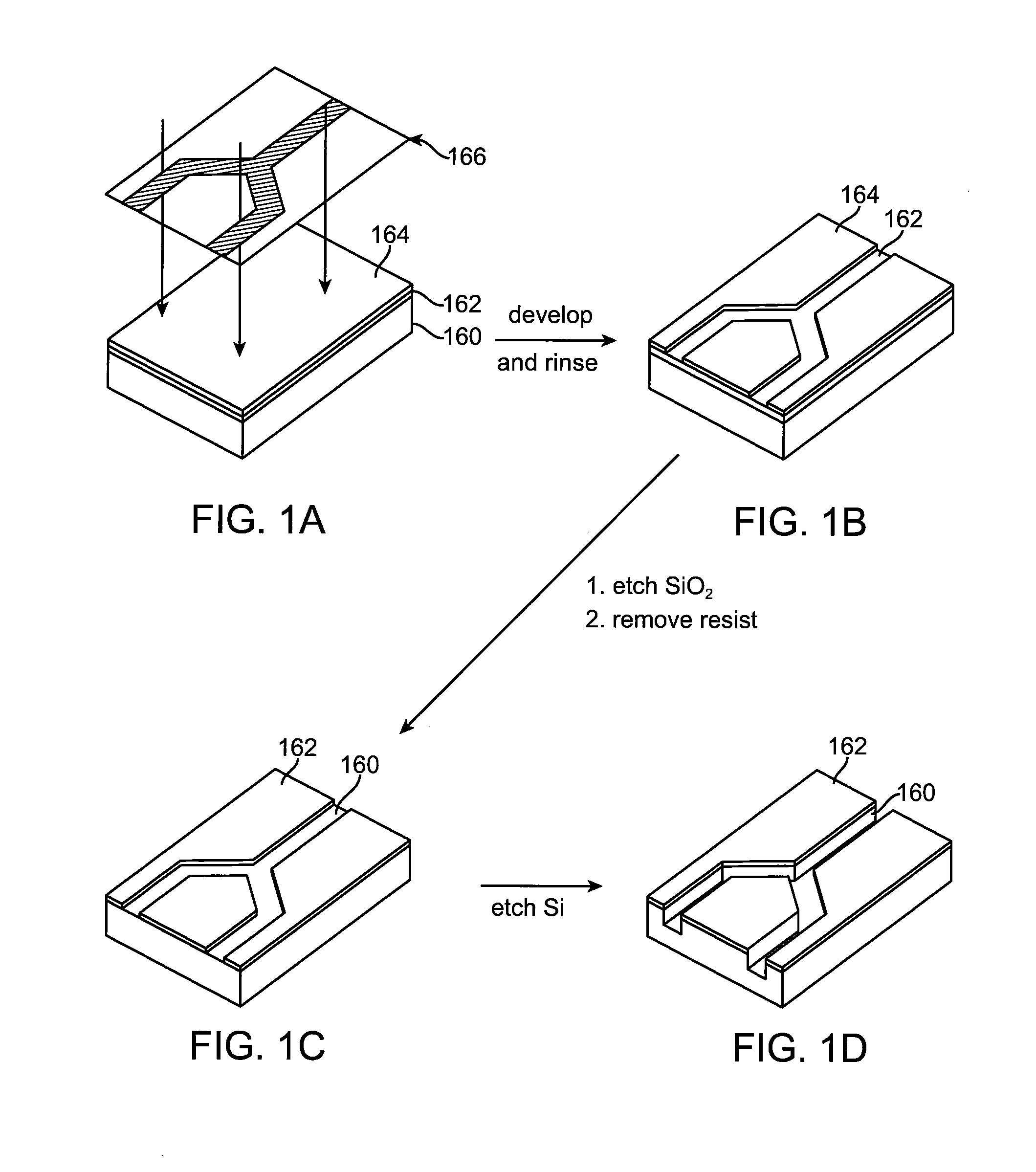
[0129]FIGS. 1A-1D illustrate the initial steps in microfabricating the channels and discrimination region of a cell sorting device of the invention by photolithographic techniques. As shown, the structure includes a silicon substrate 160. The silicon wafer which forms the substrate is typically w...

Example

EXAMPLE 2

Photodiode Detectors

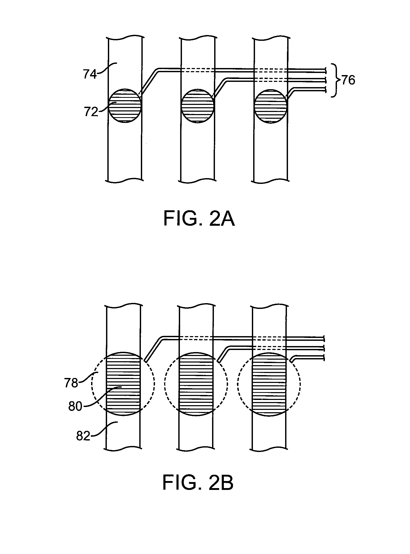
[0134]In one embodiment of the invention, shown in FIG. 2A, each detection region is formed from a portion of a channel 74 of an analysis unit and includes a photodiode 72 preferably located in the floor of the main channel. The detection region encompasses a receptive field of the photodiode in the channel, which receptive field has a circular shape. The volume of the detection region is the volume of a cylinder with a diameter equal to the receptive field of the photodiode and a height equal to the depth of the channel above the photodiode.

[0135]The signals from the photodiodes 72 can be carried to a processor via one or more lines 76, representing any form of electrical communication (including e.g. wires, conductive lines etched in the substrate, etc.). The processor acts on the signals, for example by processing them into values for comparison with a predetermined set of values for sorting the cells. In one embodiment, the values correspond to the ...

Example

EXAMPLE 3

Valve Structures

[0142]In an embodiment where pressure separation is used for discrimination of cells, valves can be used to block or unblock the pressurized flow of cells through selected channels. A thin cantilever, for example, may be included within a branch point, as shown in FIGS. 3A and 3B, such that it may be displaced towards one or the other wall of the main channel, typically by electrostatic attraction, thus closing off a selected branch channel. Electrodes are on the walls of the channel adjacent to the end of the cantilever. Suitable electrical contacts for applying a potential to the cantilever are also provided in a similar manner as the electrodes.

[0143]A valve within a channel may be microfabricated, if desired, in the form of an electrostatically operated cantilever or diaphragm. Techniques for forming such elements are well known in the art (e.g., 28, 40, 41, 24, 22). Typical processes include the use of selectively etched sacrificial layers in a multila...


PUM

PropertyMeasurementUnit
Lengthaaaaaaaaaa
Lengthaaaaaaaaaa
Lengthaaaaaaaaaa

Abstract

A microfluidic device for analyzing and/or sorting biological materials (e.g., molecules such as polynucleotides and polypeptides, including proteins and enzymes; viruses and cells) and methods for its use are provided. The device and methods of the invention are useful for sorting particles, e.g. virions. The invention is also useful for high throughput screening, e.g. combinatorial screening. The microfluidic device comprises a main channel and an inlet region in communication with the main channel at a droplet extrusion region. Droplets of solution containing the biological material are deposited into the main channel through the droplet extrusion region. A fluid different from and incompatible with the solution containing the biological material flows through the main channel so that the droplets containing the biological material do not diffuse or mix. Biological material within the droplets can be analyzed and/or sorted by detecting a predetermined characteristic of the biological sample in each droplet and sorting the droplet accordingly.

Description

[0001]This application claims priority under 35 U.S.C. § 119(e) to now abandoned U.S. Provisional Patent Application Ser. No. 60 / 246,793 filed on Nov. 8, 2000 and U.S. Provisional Patent Application Ser. No. 60 / 233,037 filed on Sep. 15, 2000, both of which are incorporated herein by reference in their entireties.[0002]Numerous references, including patents, patent applications and various publications, are cited and discussed in the description of this invention. The citation and / or discussion of such references is provided merely to clarify the description of the present invention and is not an admission that any such reference is “prior art” to the invention described herein. All references cited and discussed in this specification are incorporated herein by reference in their entirety and to the same extent as if each reference was individually incorporated by reference.FIELD OF THE INVENTION[0003]This invention relates to microfluidic devices and methods, including microfabricat...

Claims


Application Information

Patent Timeline
IPC IPC(8): C12M1/34G01N33/50B01L3/00B81B1/00B81C1/00G01N15/00G01N15/10G01N15/14G01N33/543
CPCB01L3/502784G01N15/1404G01N15/1484G01N33/54366B01L3/502761B01L3/502707Y10T436/143333B01L2200/0647B01L2200/0673B01L2300/0654B01L2300/0816B01L2300/0864B01L2400/0418B01L2400/0421B01L2400/0454B01L2400/0484B01L2400/0487G01N15/1434G01N2015/0088G01N2015/1006G01N2015/1081G01N2015/1411G01N2015/1481G01N2015/149Y10T436/118339G01N15/1459G01N35/08C12Q1/68C12M1/34B01L2200/0652B01L3/502715B01L2200/12B01L2300/12B01L2300/123B01L2400/0481B01L2400/0638G01N2015/0065
Inventor QUAKE, STEPHEN R.THORSEN, TODD
Owner CALIFORNIA INST OF TECH
Why Eureka
Try Eureka