Method for compensating for accessory loading

a technology for accessory loading and compensating, which is applied in the direction of hybrid vehicles, electrical control, instruments, etc., can solve the problems of increasing the total power demand, vsc to respond with an intrusive engine speed change, and affecting the operation of the vehicle, so as to maintain the neutrality of battery charge and maintain the high voltage battery charge balance

Active Publication Date: 2007-11-13
FORD GLOBAL TECH LLC
View PDF16 Cites 18 Cited by
  • Summary
  • Abstract
  • Description
  • Claims
  • Application Information

AI Technical Summary

Benefits of technology

[0010]In accordance with the invention, in an internal combustion engine including an advanced VSC that calculates the total engine power needed to meet the driver demand plus all accessory loads and independently schedules the engine speed and load operating point, the driver demanded wheel power is reduced (for example, by reducing driver demanded wheel torque) to compensate for the power consumed by the A / C compressor so that the VSC no longer needs to raise the engine speed to maintain the high voltage battery charge balance. It is appreciated that reducing the driver demanded wheel power in accordance with the invention may be used to compensate for any change to engine brake power not associated with a driver input that ordinarily would cause the VSC to respond with an intrusive engine speed change. Such changes may include electrical loads (for example, an electric A / C system or any other electric load) because in order to maintain battery charge neutrality it would ordinarily be necessary to increase engine speed to make up for the electric load. Further, it is appreciated that the invention is applicable to any advanced VSC; examples of powertrain systems that may have such VSCs include continuously variable transmission (CVT) and power split hybrid applications.

Problems solved by technology

Therefore, this engine speed behavior may be intrusive and disturbing to the operator of the vehicle.
The engaging of the A / C compressor clutch increases the accessory load, thus increasing the total power demand.
In general, any change to engine brake power not associated with a driver input can cause the VSC to respond with an intrusive engine speed change.

Method used


Image

  • Method for compensating for accessory loading
  • Method for compensating for accessory loading
  • Method for compensating for accessory loading

Examples


Embodiment Construction

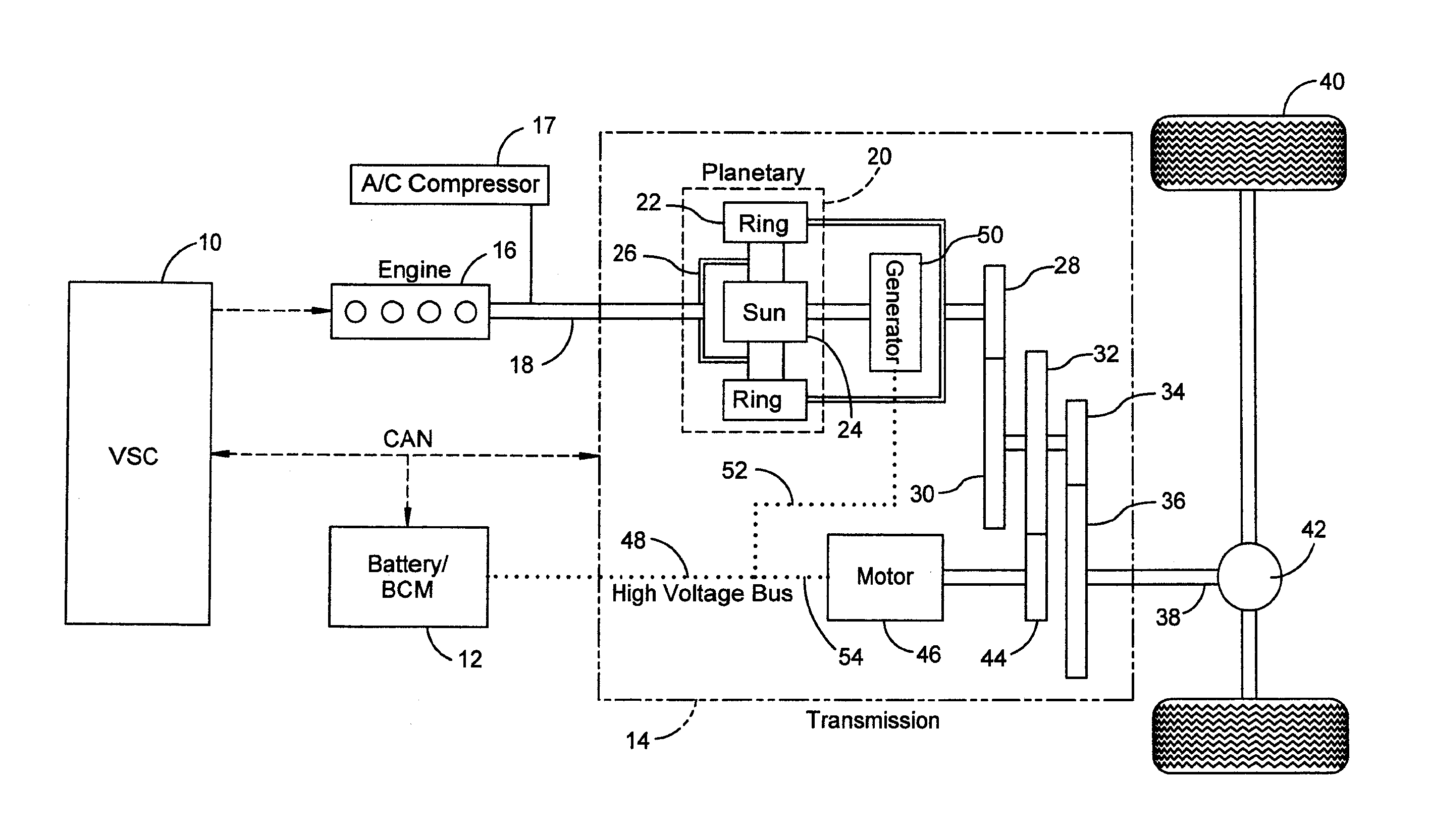
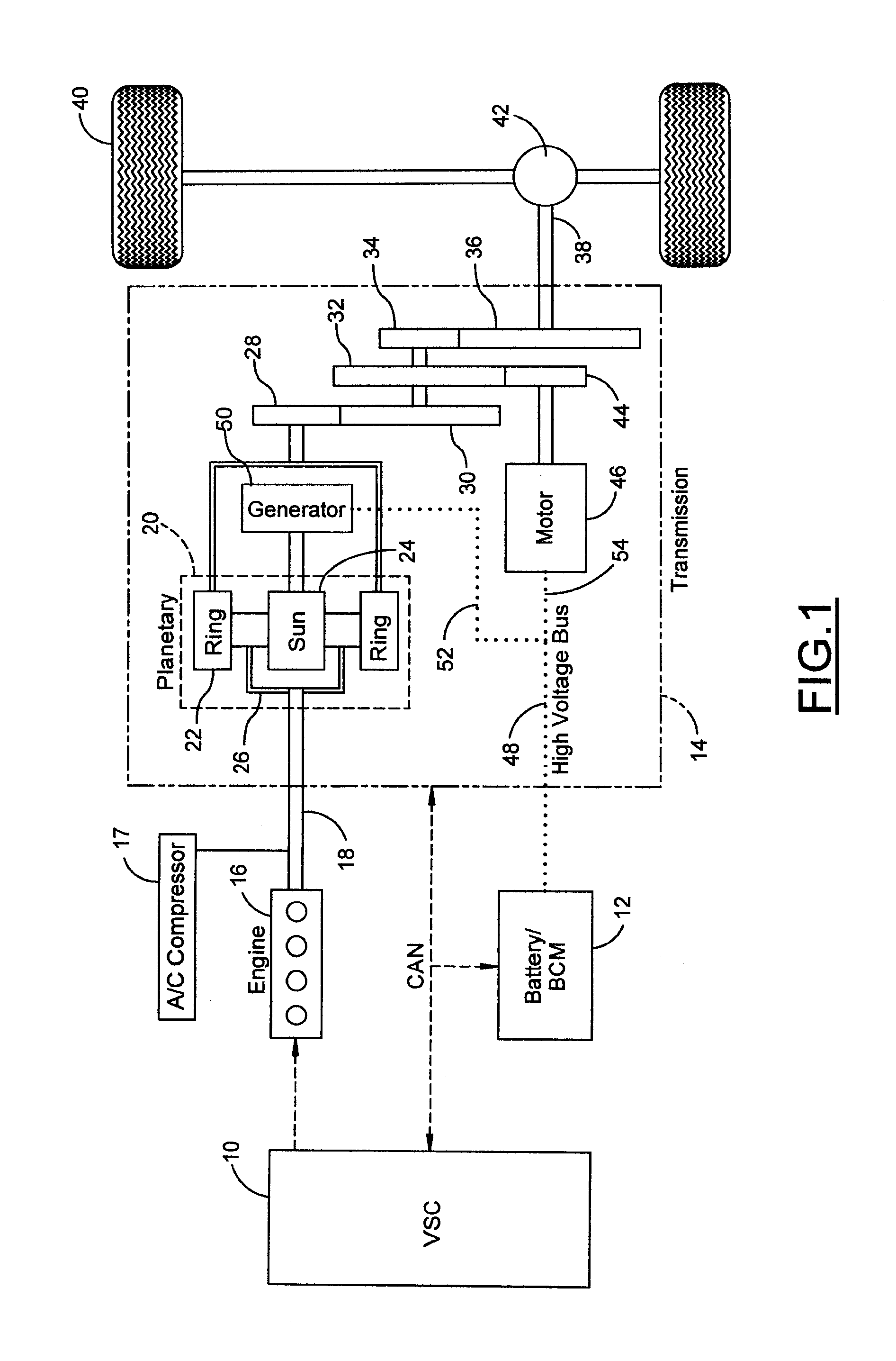
[0019]A hybrid electric vehicle powertrain is shown in FIG. 1. A vehicle system controller (VSC) 10, a battery and battery control module (BCM) 12, and a transmission 14, together with a motor-generator subsystem, comprise a control area network (CAN). An engine 16, controlled by VSC 10, distributes torque through torque input shaft 18 to transmission 14.

[0020]The transmission 14 includes a planetary gear unit 20, which comprises a ring gear 22, a sun gear 24, and a planetary carrier assembly 26. The ring gear 22 distributes torque to step ratio gears comprising meshing gear elements 28, 30, 32, 34, and 36. A torque output shaft 38 for the transmission is drivably connected to vehicle traction wheels 40 through a differential and axle mechanism 42.

[0021]Gears 30, 32, and 34 are mounted on a countershaft, with gear 32 engaging a motor-driven gear 44. Electric motor 46 drives gear 44, which acts as a torque input for the countershaft gearing.

[0022]The battery delivers electric power t...


PUM


Abstract

An internal combustion engine includes an advanced vehicle system controller (VSC) that calculates a total power demand to meet a driver wheel power demand plus any accessory loads and independently schedules an engine speed and load operating point to meet the total power demand. A reduction in available engine brake power that is not associated with a driver input, and would ordinarily cause the VSC to respond by raising engine speed, is detected. The driver wheel power demand is reduced to compensate for the reduction in available engine brake power such that the VSC does not need to raise engine speed to meet the driver wheel power demand. A magnitude of the reduction may be determined according to a calibration map to allow a trade off to be made between driveability and noise, vibration, and harshness.

Description

BACKGROUND OF THE INVENTION[0001]1. Field of the Invention[0002]The invention relates to an internal combustion engine which includes an advanced vehicle system controller (VSC) that calculates the total engine power needed to meet the driver demand plus all accessory loads and independently schedules the engine speed and load operating point, with or without feedback of actual engine performance, to meet the total power demand.[0003]2. Background Art[0004]In an existing internal combustion engine including an advanced vehicle system controller (VSC), the VSC calculates the total engine power needed to meet the driver wheel power demand plus all accessory loads, and independently schedules the engine speed and load operating point, with or without feedback of actual engine performance, to meet the total power demand. By scheduling the most efficient engine speed and load operating point, the VSC may attempt to maximize fuel economy. Examples of powertrain systems which may involve V...

Claims


Application Information

Patent Timeline
Patent Type & Authority Patents(United States)
IPC IPC(8): F02D29/06F02N11/08B60K6/445B60K6/448F02N99/00
CPCB60K6/365B60K6/445B60W10/06B60W10/30F02D41/083F02D41/12B60K1/02Y02T10/6239B60W2550/12F02D2200/1006B60W20/00B60W2555/20Y02T10/62B60W2510/0638B60W20/10B60W2510/069
Inventor OKUBO, SHUNSUKESYED, FAZAL
Owner FORD GLOBAL TECH LLC
Why Eureka
Try Eureka