Method and a device for monitoring a medical microsample in the flow measuring cell of an analyzer

a flow cell and microsample technology, applied in the field of monitoring systems, can solve the problems of insufficient flow cells and errors in measurement results, and achieve the effect of simple design and reliable measurement results

Active Publication Date: 2007-11-20
ROCHE DIAGNOSTICS OPERATIONS INC
View PDF26 Cites 102 Cited by
  • Summary
  • Abstract
  • Description
  • Claims
  • Application Information

AI Technical Summary

Benefits of technology

[0004]It is against the above background that the present invention provides certain unobvious advantages and advancements over the prior art. In particular, the inventors have recognized a need to improve methods and / or devices for monitoring the positioning and the absence of bubbles in a medical microsample in the flow cell of an analyzer in such a way, that reliable measurement results may be obtained in flow cells with a multitude of electrode systems and that a simple design is guaranteed.
[0013]Simultaneous measurement offers the advantage that a change in the sample taking place during analyte measurement (e.g., gas formation at the working electrode, change in pH value, etc.) may be monitored via the simultaneous conductance measurement at the exact point in time of the analyte measurement.
[0014]In accordance with the various embodiments of the present invention, repetitive measurements of microsamples with short cycle times may be carried out with high precision and reliability. The occurrence of gas bubbles can be recognized immediately during the measurement process and may thus be taken into account. A further advantage in comparison to measurement with one-way sensors lies in the fact that in serial measurements the time-consuming and awkward replacement of the sensors, which often entails a time-intensive calibration of the sensor, is avoided.
[0015]In accordance with the various embodiments of the present invention, the possibility to determine the position of the sample during measurement permits a substantial reduction in sample volume as compared with state-of-the-art methods; an advantage which becomes increasingly important as the number of analytes to be measured increases.

Problems solved by technology

Due to the distance between the electrodes for the measurement proper and the electrodes for position-checking, errors in the measurement result may occur.
It is for instance not sufficient in this type of flow cells to check the positioning of the sample prior to measuring, as it will of course change during the measurement process.
A further problem occurs if electrochemical reactions due to the measurement voltage cause bubble formation at an electrode, which is undesirable and may result in measurement errors.

Method used


Image

  • Method and a device for monitoring a medical microsample in the flow measuring cell of an analyzer
  • Method and a device for monitoring a medical microsample in the flow measuring cell of an analyzer
  • Method and a device for monitoring a medical microsample in the flow measuring cell of an analyzer

Examples


Embodiment Construction

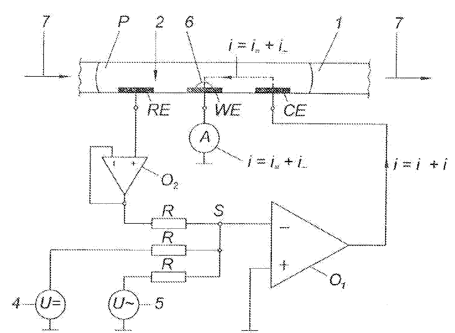
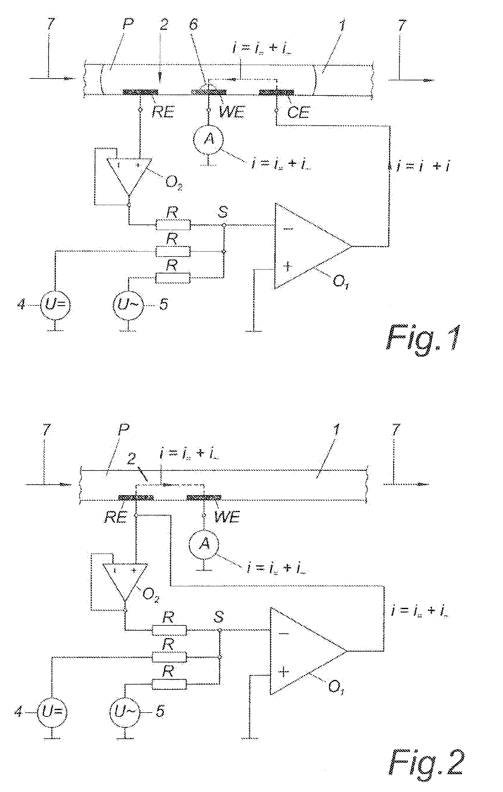
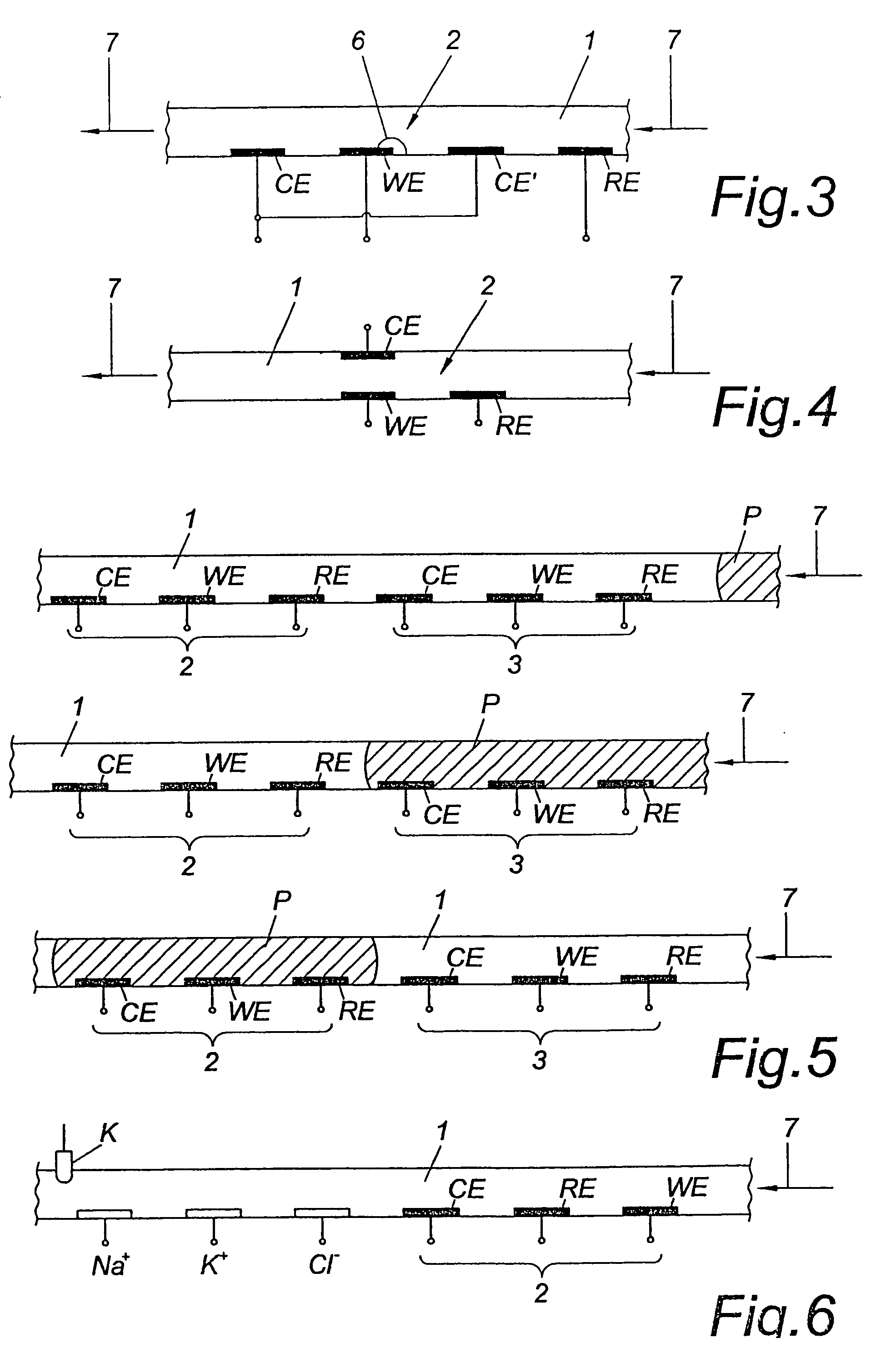
[0029]FIG. 1 presents the first variant of a device for the monitoring of position and bubble formation in a medical microsample P in a flow cell or measurement capillary 1 of an analyzer not shown here in detail, where the counter-electrode CE and the working electrode WE of an amperometric electrode system 2 are used as contact points between which the impedance or conductance of the microsample is measured, for instance for the measurement of glucose concentration in a blood sample. Further electrode systems may be placed behind electrode system 2 but are not shown in the drawing.

[0030]The circuit realizes a potentiostatic design based on the addition principle. By using an adder the target value of the voltage at the reference electrode RE may be built up by superposition of a number of different input voltages. The operational amplifier O1 varies its output voltage (corresponding to the voltage at the counter-electrode CE) until the sum of the currents at the summation point S(...


PUM

PropertyMeasurementUnit
frequencyaaaaaaaaaa
DC voltageaaaaaaaaaa
alternating voltageaaaaaaaaaa

Abstract

The invention relates to a method and device for the monitoring of a medical microsample in the flow measuring cell of an analyzer with regard to position and absence of bubbles by means of an alternating voltage applied to the measuring cell, the measuring cell being provided with a multitude of electrode systems placed one behind the other, each system comprising a number of single electrodes for measuring a substance contained in the microsample by means of a measurement voltage which essentially is a DC voltage. To monitor the exact position of the microsample and / or to detect air bubbles in the area of each electrode system, the alternating voltage and the measurement voltage are simultaneously and directly applied to the single electrodes of the corresponding electrode system, and the measured AC component respectively the measured impedance gives a measure for the position of the microsample and the absence of bubbles.

Description

FIELD OF THE INVENTION[0001]The present invention relates to monitoring systems and methods thereof, and in particular to a device and method for monitoring a medical microsample in the flow measuring cell of an analyzer.BACKGROUND OF THE INVENTION[0002]In measuring medical samples a fundamental distinction is made between one-way sensors and flow measuring cells. In the case of a one-way sensor the sample is introduced into the sensor and brought into contact with measuring electrodes. The basic requirement for an accurate and error-free measurement is a suitable positioning of the sample in the measuring cell. It is a known procedure to check the positioning via special measuring contacts, to which an AC voltage is applied, such that an impedance measurement will produce a signal which provides information regarding the position of the sample. Due to the distance between the electrodes for the measurement proper and the electrodes for position-checking, errors in the measurement r...

Claims


Application Information

Patent Timeline
Patent Type & Authority Patents(United States)
IPC IPC(8): G01N27/327G01N27/02G01N27/10G01N27/416G01N27/403G01N35/10
CPCG01N27/10G01N2035/1018
Inventor KONTSCHIEDER, HEINZHUEMER, HERFRIEDHAJNSEK, MARTIN
Owner ROCHE DIAGNOSTICS OPERATIONS INC
Why Eureka
Try Eureka