RFID tag with enhanced readability

a radio frequency identification and readability technology, applied in the direction of instruments, resonant antennas, burglar alarm mechanical actuation, etc., can solve the problems of difficult readability high dependence on its orientation, and difficulty in reading along the edge of the device b>1/b>, especially parallel to the direction of the antenna elements b>4/b> and b>5/b>, so as to enhance the performance of the devi

Active Publication Date: 2007-11-20
AVERY DENNISON CORP
View PDF40 Cites 125 Cited by
  • Summary
  • Abstract
  • Description
  • Claims
  • Application Information

AI Technical Summary

Benefits of technology

[0012]According to still another aspect of the invention, a method of communicating with one or more of plural RFID devices, the method comprising: enhancing performance of the devices by bringing the devices in close proximity to one another; and communicating with wireless communication devices of the one or more of the devices.
[0013]According to a further aspect of the invention, performance of RFID devices is enhanced by the devices being brought in close proximity to one another.

Problems solved by technology

One difficulty with the simple dipole antenna structure 3 illustrated in FIG. 1 is that the readability of the structure may be highly dependent on its orientation.
For instance, readability of the device 1 along its edges, especially parallel to the direction of the antenna elements 4 and 5, along a narrow axis 8 of the device 1, may be difficult.

Method used


Image

  • RFID tag with enhanced readability
  • RFID tag with enhanced readability
  • RFID tag with enhanced readability

Examples


Embodiment Construction

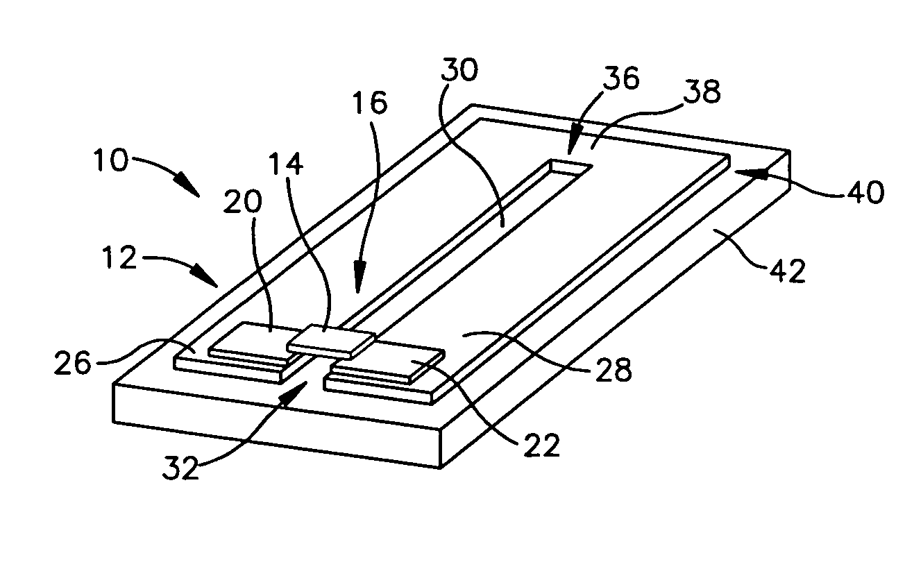
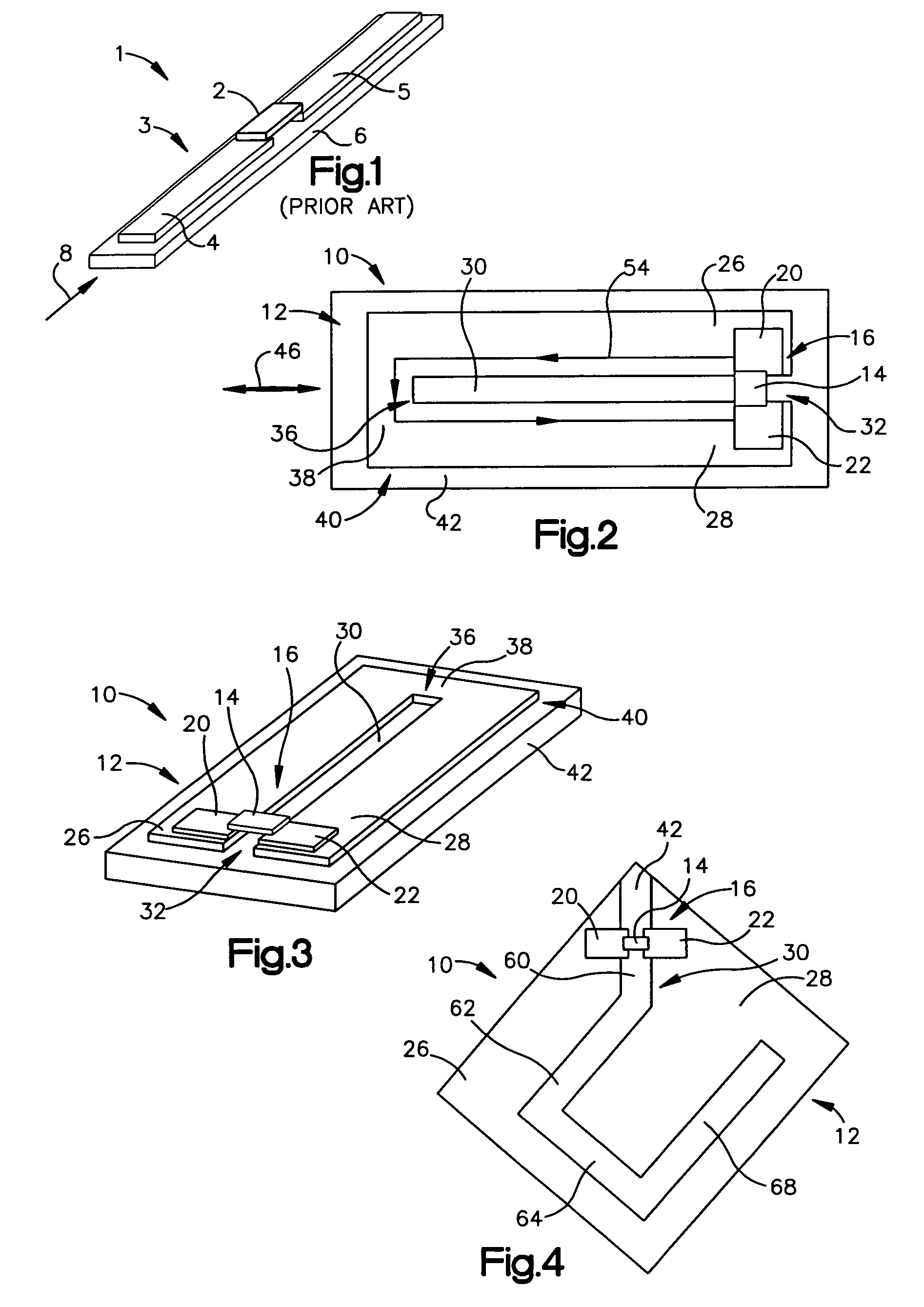
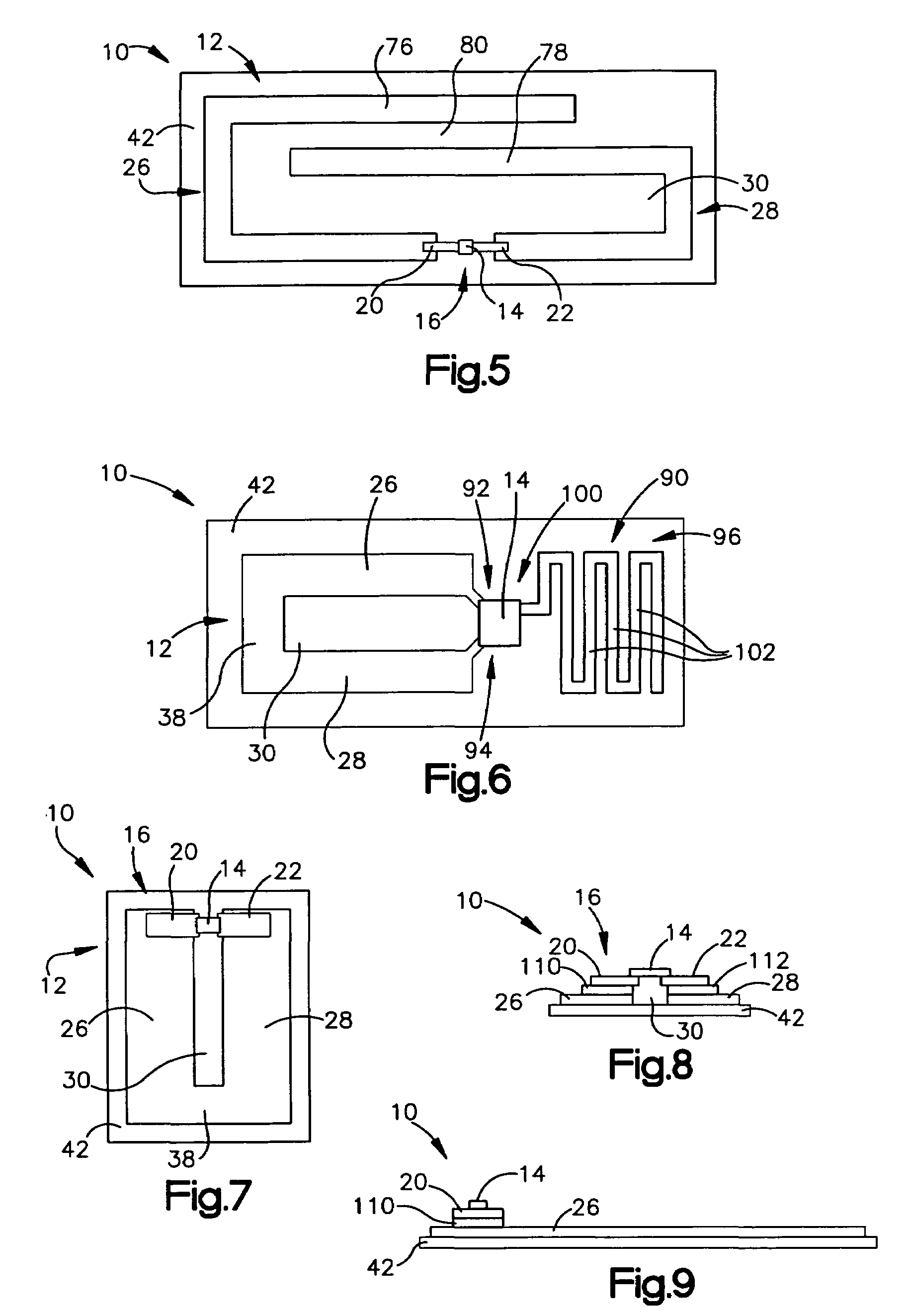
[0055]A radio frequency identification (RFID) device includes a conductive antenna structure having an elongated slot therein. Parts of the antenna structure on both sides of one end of the elongated slot are coupled to a wireless communication device, such as an RFID chip or interposer. On the opposite end of the elongated slot, parts of the antenna structure at both sides of the elongated slot are electrically coupled together, for instance by being coupled together by other conductive parts of the antenna structure. All of the parts of the antenna structure may be parts of a continuous unitary layer of conductive material. The antenna structure with the elongated slot therein may facilitate increased readability of the RFID device, particularly in directions out from the edges of the RFID device. The antenna structure may be directly conductively coupled to the wireless communication device. Alternatively, the antenna structure may be indirectly (reactively) coupled to the RFID d...


PUM


Abstract

A radio frequency identification (RFID) device includes a conductive antenna structure having an elongated slot therein. Parts of the antenna structure on both sides of one end of the elongated slot are coupled to a wireless communication device, such as an RFID chip or interposer. On the opposite end of the elongated slot, parts of the antenna structure at both sides of the elongated slot are electrically coupled together, for instance by being coupled together by other conductive parts of the antenna structure. All of the parts of the antenna structure may be parts of a continuous unitary layer of conductive material. The antenna structure with the elongated slot therein may facilitate increased readability of the RFID device, particularly in directions out from the edges of the RFID device.

Description

CROSS-REFERENCE TO RELATED APPLICATIONS[0001]Priority is claimed under 35 USC 119(e) to U.S. Provisional Application No. 60 / 517,155, filed Nov. 4, 2003, which is incorporated herein by reference in its entirety.BACKGROUND OF THE INVENTION[0002]1. Field of the Invention[0003]This invention relates to the field of Radio Frequency Identification (RFID) tags and labels, and in particular to tags and labels that include an antenna structure.[0004]2. Description of the Related Art[0005]Current inventory and manufacturing methods rely on the ability to track and identify items of concern, such as inventory items, packages, individual parts, etc., and to communicate information concerning such items of concern in a wireless manner for processing and use. One known method of tracking and providing information on such items of concern is to attach to each such item a wireless communication device, such as an active or passive transponder, incorporated into an identification tag or label that ...

Claims


Application Information

Patent Timeline
Patent Type & Authority Patents(United States)
IPC IPC(8): H01Q13/10G06K19/077H01Q1/22H01Q1/24H01Q1/27H01Q1/38H01Q7/00H01Q9/26H01Q9/42H01Q13/00H04Q5/22
CPCG06K19/07749G06K19/07771G06K19/07796H01Q1/22H01Q1/2225H01Q13/00H01Q1/273H01Q1/38H01Q7/00H01Q9/26H01Q9/42H01Q1/243G06K19/00G06K19/07
Inventor FORSTER, IAN J.PULESTON, DAVID J.
Owner AVERY DENNISON CORP
Why Eureka
Try Eureka