Portal imaging using modulated treatment beam

a beam and treatment beam technology, applied in the field of radiation therapy equipment, can solve the problems of irradiating a significant volume of non-tumorous or healthy tissue, affecting the quality of life of patients, so as to achieve the effect of improving quality

Active Publication Date: 2007-11-20
WISCONSIN ALUMNI RES FOUND
View PDF13 Cites 16 Cited by
  • Summary
  • Abstract
  • Description
  • Claims
  • Application Information

AI Technical Summary

Problems solved by technology

However, internal-source radiation therapy has the disadvantages of any surgically invasive procedure, including discomfort to the patient and risk of infection.
External-source radiation therapy avoids some of the problems of internal-source radiation therapy, but it undesirably and necessarily irradiates a significant volume of non-tumorous or healthy tissue in the path of the radiation beam along with the tumorous tissue.
Image quality, however, is significantly worse than that routinely achieved in low energy diagnostic x-ray imaging devices for two main reasons, both related to energies of the photons in the beam.
First, most of the contrast in a low energy diagnostic x-ray image comes from the photoelectric effect.
3E29 electrons / cc) are therefore discernable in high energy x-ray images, but contrast is much poorer.
The second problem with high energy x-ray imaging is the nature of Compton interactions versus photoelectric interactions.

Method used


Image

  • Portal imaging using modulated treatment beam
  • Portal imaging using modulated treatment beam
  • Portal imaging using modulated treatment beam

Examples


Embodiment Construction

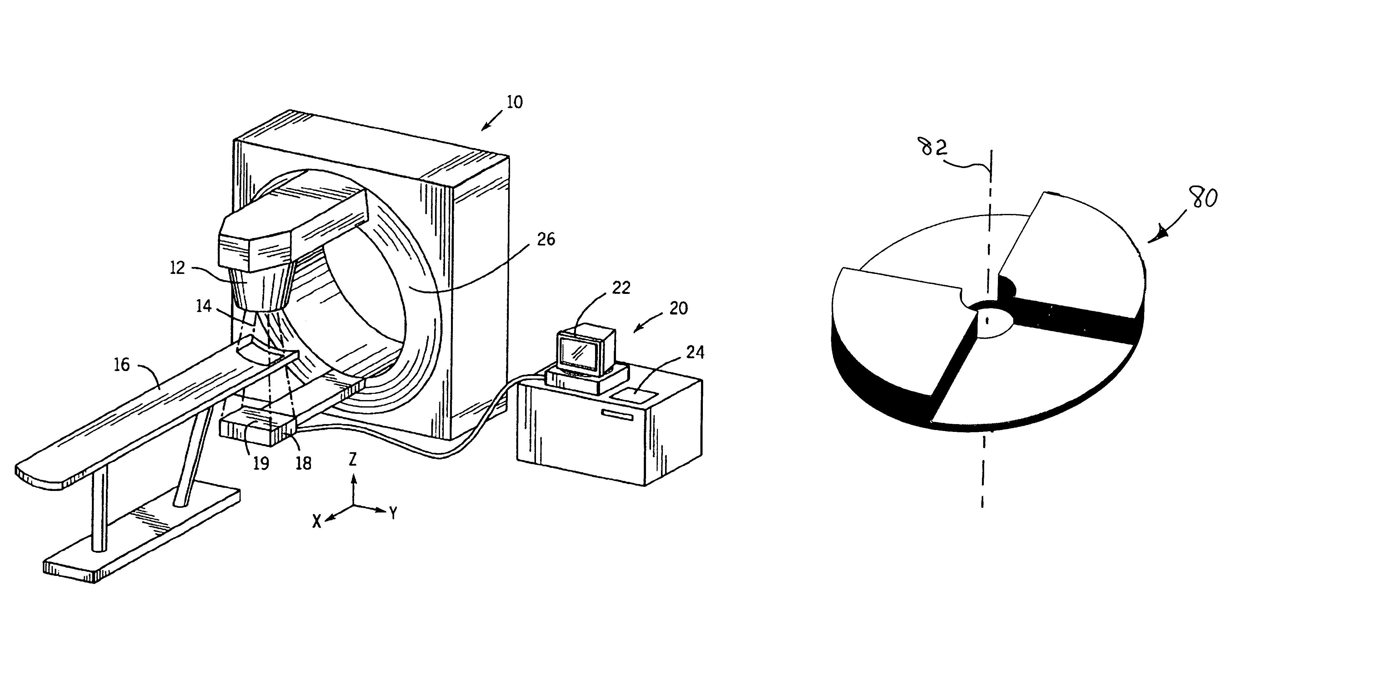
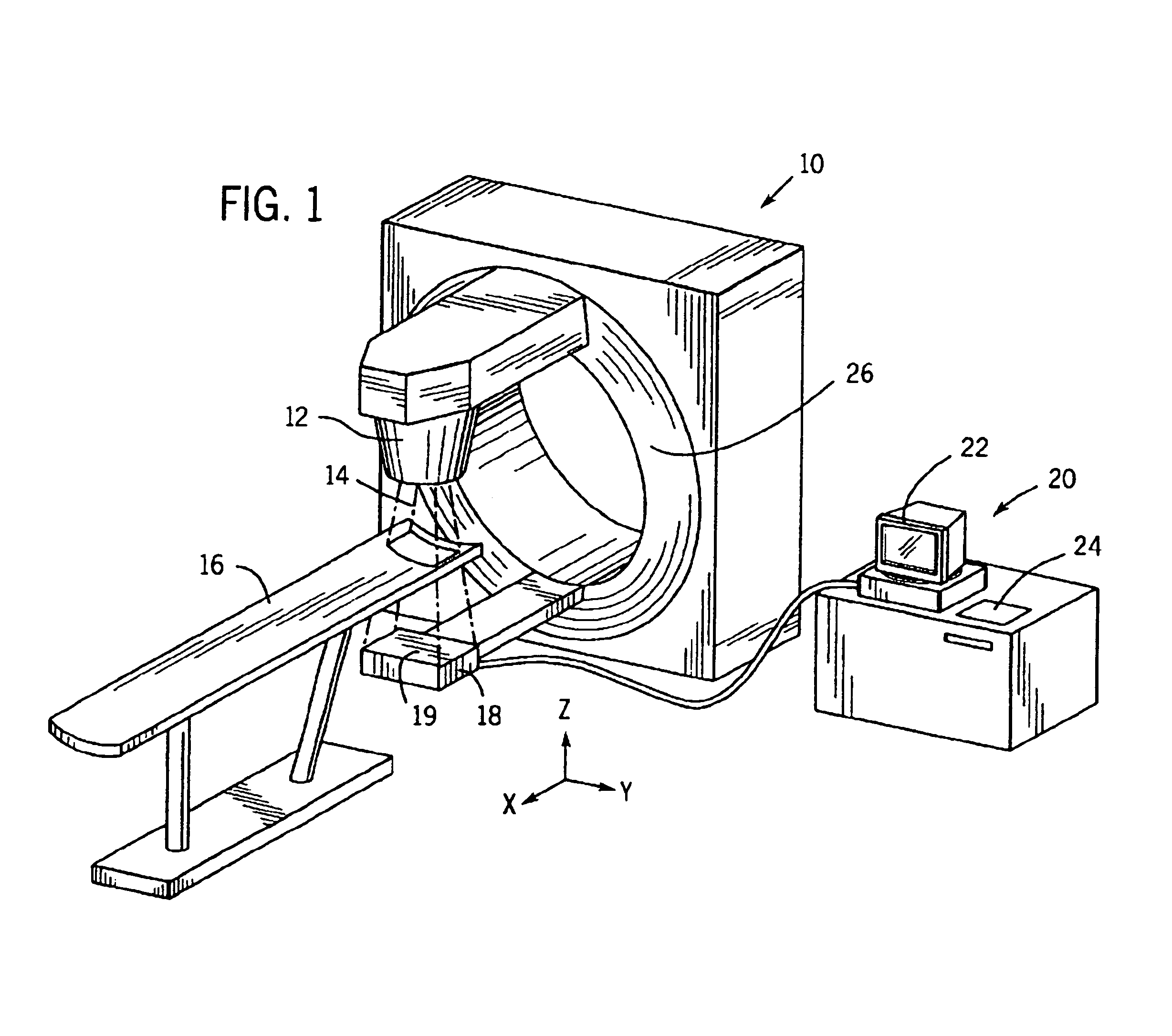
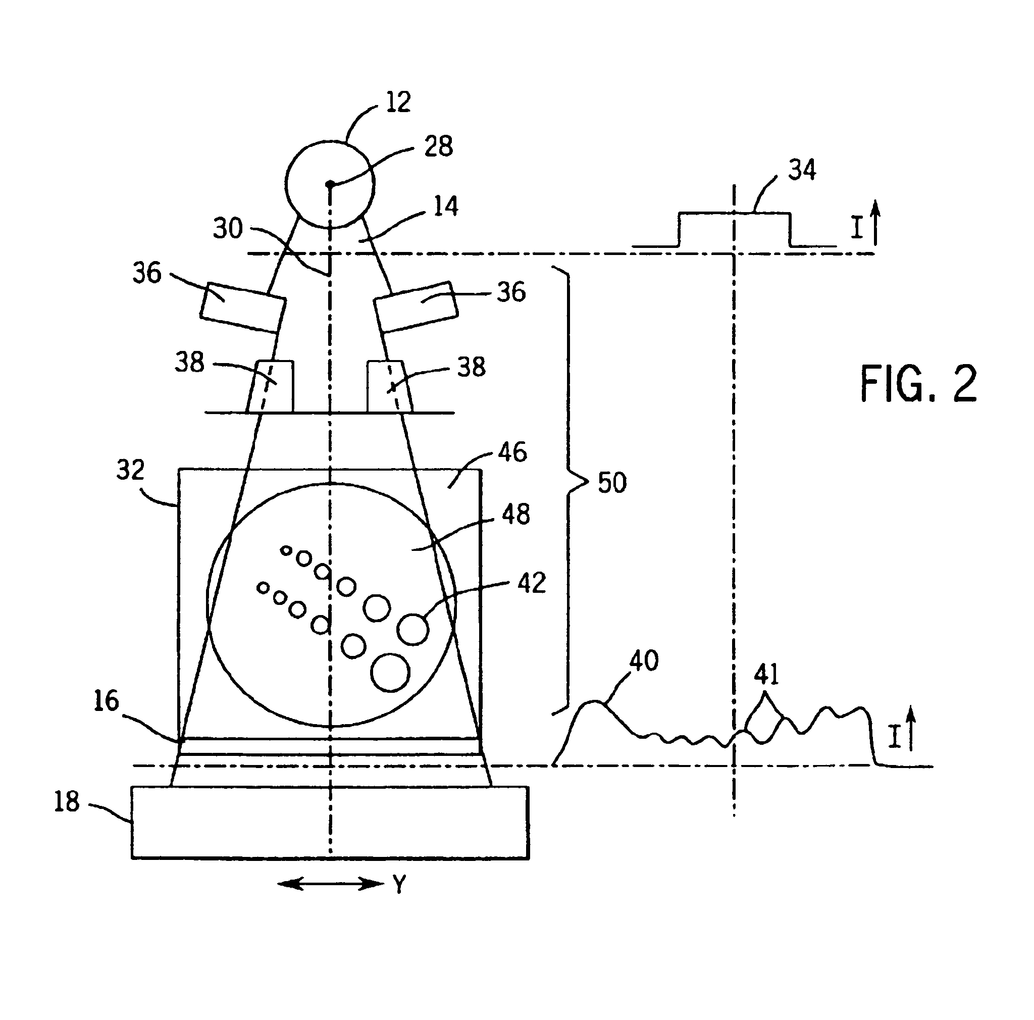
[0021]Referring to FIG. 1, a radiation therapy system 10, suitable for use in the present invention, includes a radiation source 12 producing a radiation beam 14 directed across a patient support table 16 that may hold a patient (not shown) or a calibration phantom 32 (shown in FIG. 2). The radiation beam 14 may be a megavoltage x-ray beam (e.g., 6-10 megavolts) or other photon source suitable for radiation therapy. The radiation beam 14, as shown, is collimated to a fan shape; however, the invention is equally applicable to “cone beams” of radiation.

[0022]After passing through the patient support table 16 and either the patient or a calibration phantom 32, the beam 14 is received by an electronic portal imaging device (EPID) 18 having a detector surface 19 corresponding to the cross-sectional area of the beam 14. EPID 18 produces electronic signals providing measurements of the dose of the radiation received at regularly spaced positions, or pixel locations over the detector surfac...


PUM

PropertyMeasurementUnit
photon energyaaaaaaaaaa
energyaaaaaaaaaa
thickaaaaaaaaaa

Abstract

A radiation therapy system produces a treatment beam that is detected by an electronic portal imaging device (EPID) after it passes through the subject being treated. A chopper wheel modulates low energy components of the beam while leaving the higher energy components substantially unmodulated. Modulated components in the image signals produced by the EPID are detected and used to produce portal images.

Description

STATEMENT REGARDING FEDERALLY SPONSORED RESEARCH[0001]This invention was made with government support under Grant No. 5T32 CA09 206-27 awarded by the National Institute of Health. The United States Government has certain rights in this invention.BACKGROUND OF THE INVENTION[0002]This invention relates to radiation therapy equipment for the treatment of tumors or the like and specifically to an improved method of characterizing the radiation beam of such systems and confirming the dose received by the patient using a portal image of radiation exiting the patient.[0003]Medical equipment for radiation therapy treats tumorous tissue with high energy radiation. The dose and the placement of the dose must be accurately controlled to insure both that the tumor receives sufficient radiation to be destroyed, and that damage to the surrounding and adjacent non-tumorous tissue is minimized.[0004]Internal-source radiation therapy places capsules of radioactive material inside the patient in prox...

Claims


Application Information

Patent Timeline
Patent Type & Authority Patents(United States)
IPC IPC(8): G01N23/04A61N5/10
CPCA61N5/1048G21K1/043A61N2005/1054
Inventor NELSON, IAN A.
Owner WISCONSIN ALUMNI RES FOUND
Why Eureka
Try Eureka