Target recognizing device and target recognizing method

a target recognition and target technology, applied in image analysis, instruments, computing, etc., can solve the problems of difficult to perform accurate target recognition processing of targets in scenes

Active Publication Date: 2007-11-20
HONDA MOTOR CO LTD
View PDF13 Cites 21 Cited by
  • Summary
  • Abstract
  • Description
  • Claims
  • Application Information

AI Technical Summary

Benefits of technology

[0010]It is an object of the present invention to provide a target recognizing device and a target recognizing method, which can self-generate a template

Problems solved by technology

In other words, there is a problem in that before conducting the recognition processing, it is necessary to store the templates for the number of types of target, being an object to be recognized, beforehand in the target recognizing device.
Therefore, even by simply using the optical flow, it is difficult to

Method used


Image

  • Target recognizing device and target recognizing method
  • Target recognizing device and target recognizing method
  • Target recognizing device and target recognizing method

Examples


Embodiment Construction

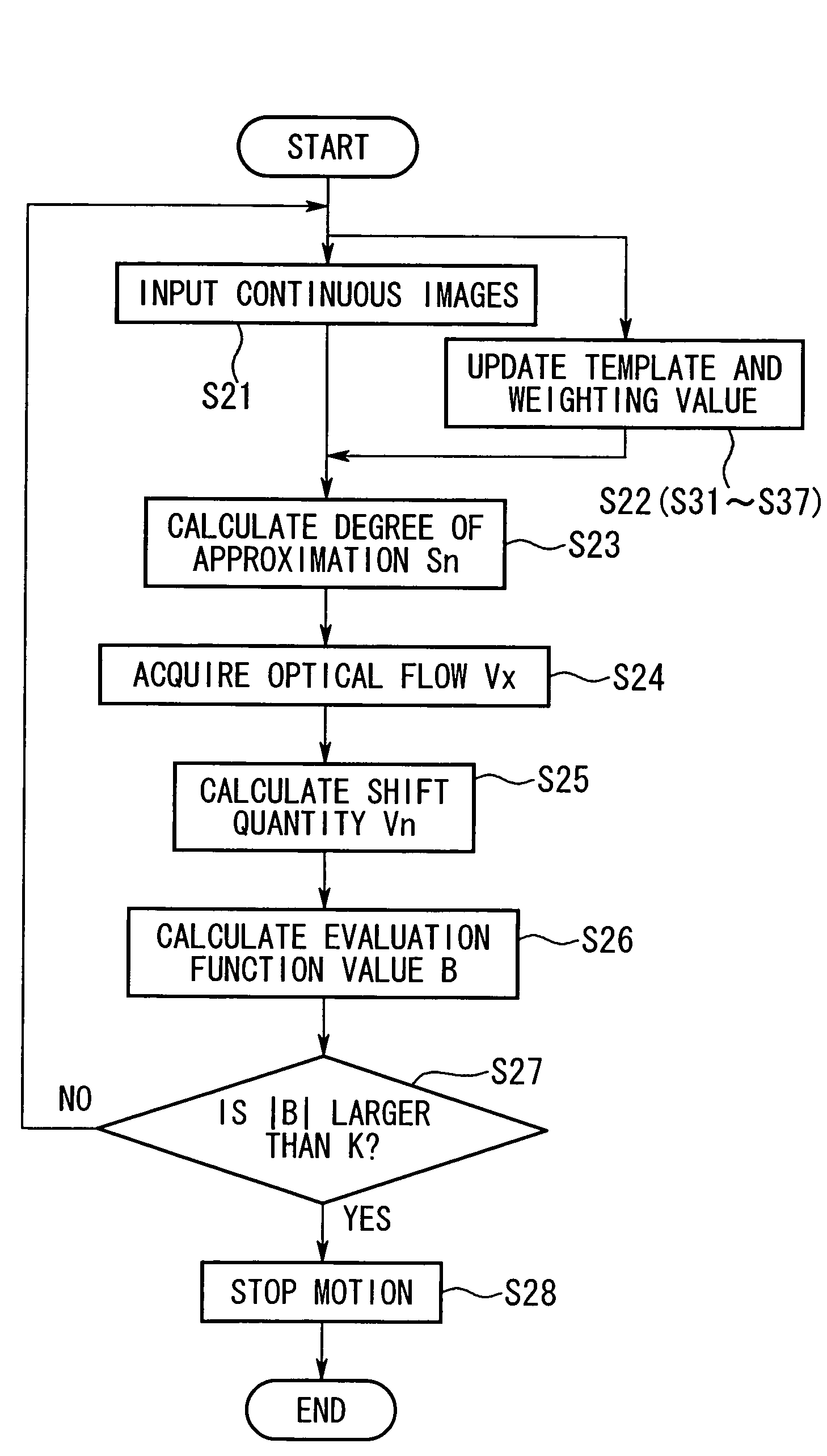
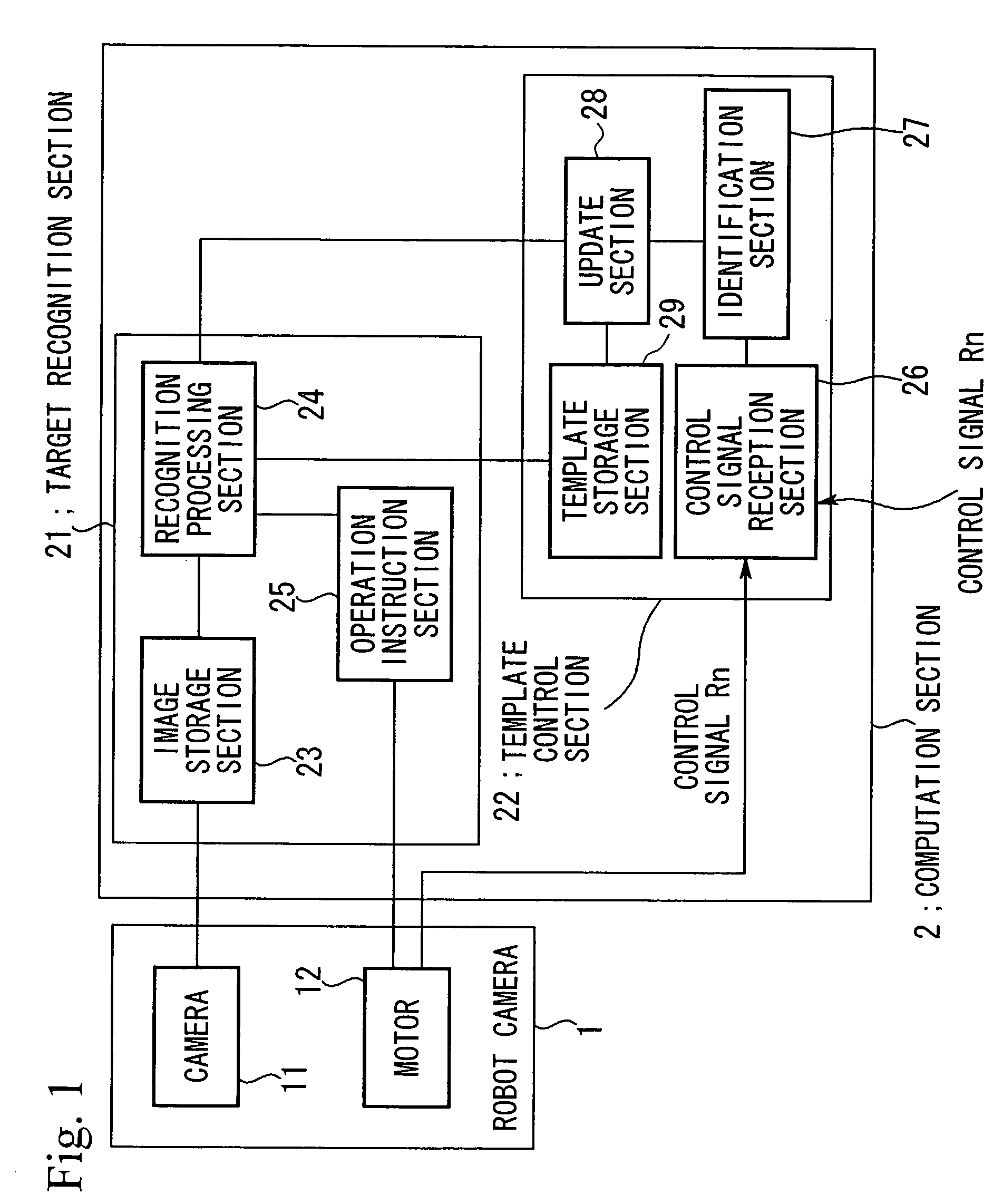
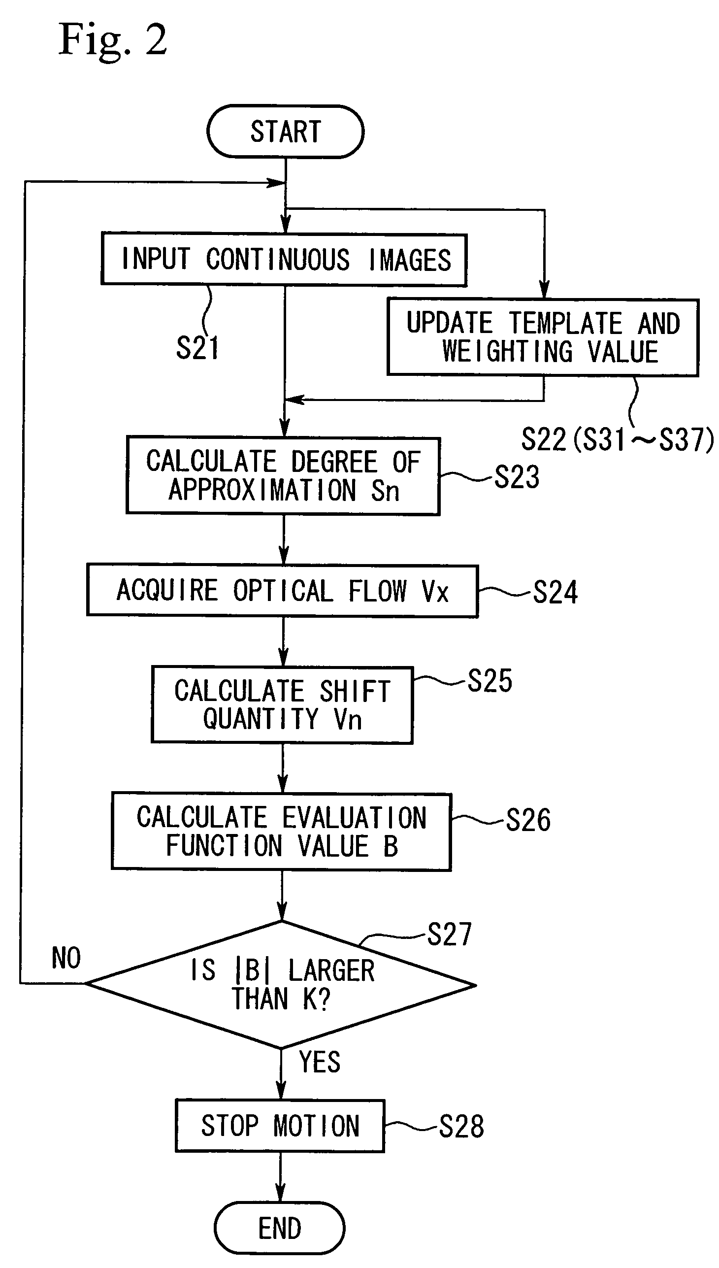
[0040]The target recognizing device according to one embodiment of the present invention will be described, with reference to the drawings. FIG. 1 is a block diagram showing the configuration of this embodiment. Reference symbol 1 denotes a robot camera comprising a camera 11 (for example, a CCD camera) for acquiring peripheral images, and a motor 12 for rotating the camera 11 in the horizontal direction to direct the optical axis of the camera 11 to an optional direction. The motor 12 is provided with an encoder (not shown), so that the direction (angle of rotation) of the camera 11 at the time of rotational motion can be detected by a value of the encoder. Reference symbol 2 denotes an arithmetic operation section, which comprises a target recognition section 21 and a template control section 22. Reference symbol 23 denotes an image storage section for storing images taken by the camera 11, and images stored herein are sampled and quantized images. Reference symbol 24 denotes a re...


PUM


Abstract

A target recognizing device that creates a template concerning a target by itself is provided. The device comprises a robot camera for creating continuous images showing a target and an arithmetic operation unit for controlling the robot camera. A robot camera acquires continuous image information by means of a camera rotatable by a motor. The arithmetic operation unit comprises a template management section for allowing an update part to update a template stored in a template storage part and a target recognition section having an image storage part where the acquired image information is stored, a recognizing part for recognizing a target by using the template, and a motion command part for rotating a camera according to the result of recognition.

Description

[0001]This application is the national phase under 35 U.S.C. §371 of PCT International Application No. PCT / JP02 / 01199 which has an International filing date of Feb. 13, 2002, which designated the United States of America.TECHNICAL FIELD[0002]The present invention relates to a target recognizing device and a target recognizing method for recognizing a target by using templates.[0003]This application is based on a patent application in Japan (Japanese Patent Application No. 2001-042299), and the contents in the application in Japan are hereby incorporated as a part of this specification.BACKGROUND ART[0004]In conventional image recognizing devices, various sensors such as a camera are used to obtain a scene including a target, being an object to be recognized, as image information, and target recognition is conducted based on the image information and fragmentary knowledge with respect to the target. The main object of the target recognition is to grasp the scene including the target ...

Claims


Application Information

Patent Timeline
IPC IPC(8): G06K9/62G06K9/00G06K9/68G06V10/772
CPCG06K9/6255G06T7/2066G06T7/2006G06T7/215G06T7/269G06V10/772G06F18/28
Inventor HASEGAWA, YUJI
Owner HONDA MOTOR CO LTD
Why Eureka
Try Eureka