Electronic control device for aviation engine

a technology of electronic control device and aviation engine, which is applied in the direction of electric control, ignition automatic control, instruments, etc., can solve the problems of error, inability to control ignition control and fuel injection for two cylinders, and high redundancy

Inactive Publication Date: 2007-11-20
HONDA MOTOR CO LTD
View PDF6 Cites 6 Cited by
  • Summary
  • Abstract
  • Description
  • Claims
  • Application Information

AI Technical Summary

Benefits of technology

[0022]In order to resolve the aforementioned problems, it is the object of the present invention to bring about a high level of redundancy with a small number of CPU's, so as to provide an electronic control device for an aviation engine with few limitations placed in relation to installation location.
[0027]According to the present invention, the following effects are achieved:
[0030]According to the third aspect of the invention, it is possible to carry out ignition control in parallel using each CPU. This means that even if a lane including one CPU malfunctions, it is possible to continue ignition control using the lane including the other CPU without carrying out lane switching.

Problems solved by technology

(1) An expensive CPU is required for each of the cylinders.
(2) Each ECU only carries out control of two cylinder sections. This means that ignition control and fuel injection control for two cylinders is not possible when, for example, there is an accident such as damage or disengagement etc. of a connector for the sensor input interface.
(3) Each CPU operates independently. This means that in cases where complex ignition control such as lag angle control and advance angle control etc. is carried out taking not only crank and cam timing but also detection signals such as for an intake negative pressure sensor or nock sensor etc. as parameters, errors occur in the results of calculations of each CPU. As a result, in the case of ignition control, a shift occurs in the ignition timing of the main ignition plug and the ignition timing of the back-up ignition plug at each cylinder.
(4) The casing for the ECU is large for the type where an ignition coil is built into the ECU and restrictions on the fitting position are therefore substantial. When the ECU is fitted at a position away from the engine, the distance between the ignition coil and the ignition plug becomes substantial and the long high tension cable is therefore necessary. Because of this, not only is secondary energy loss in ignition substantial and a fall in voltage supplied to the ignition plug invited, but also influence on emission performance is substantial.

Method used


Image

  • Electronic control device for aviation engine
  • Electronic control device for aviation engine
  • Electronic control device for aviation engine

Examples


first embodiment

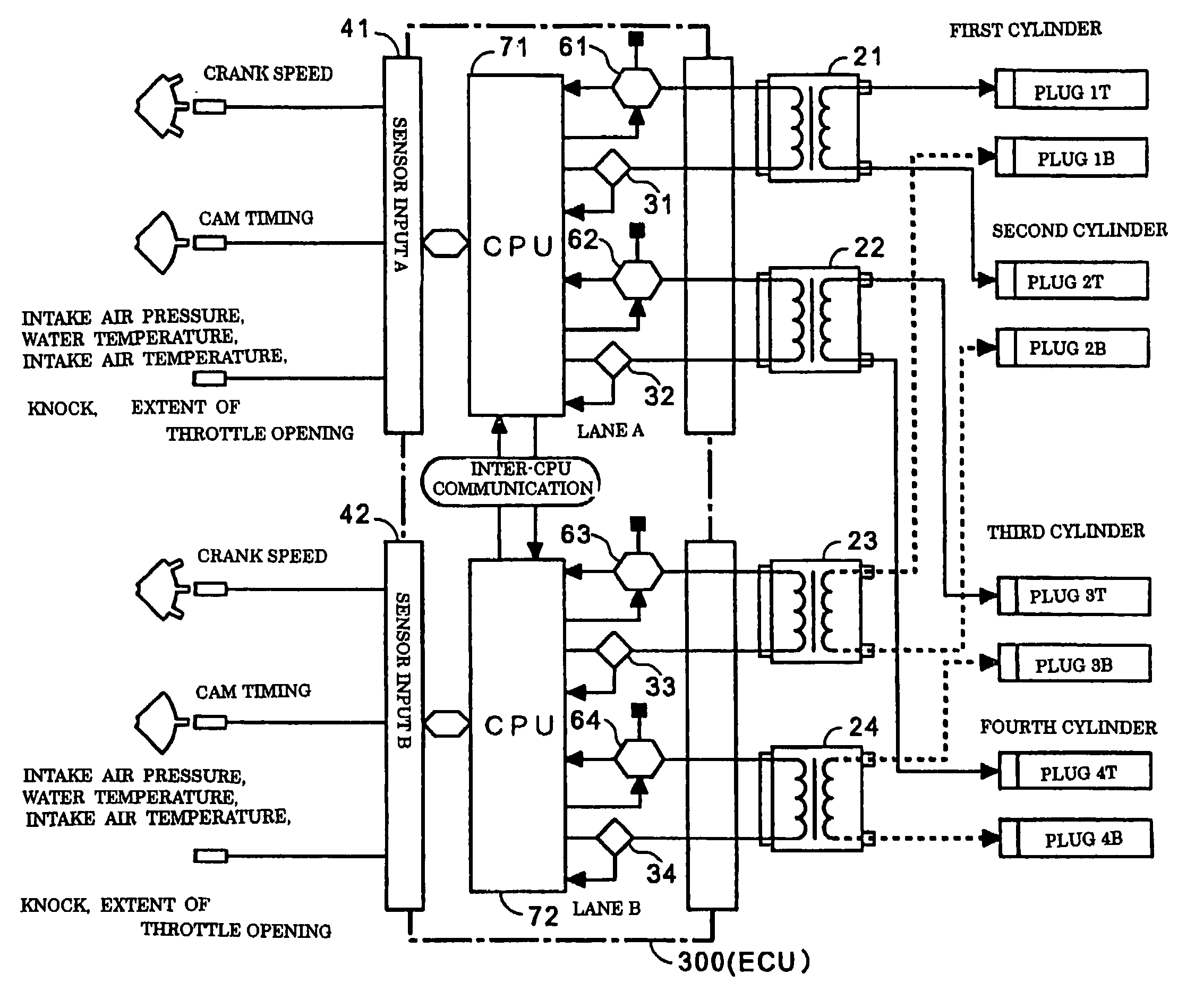
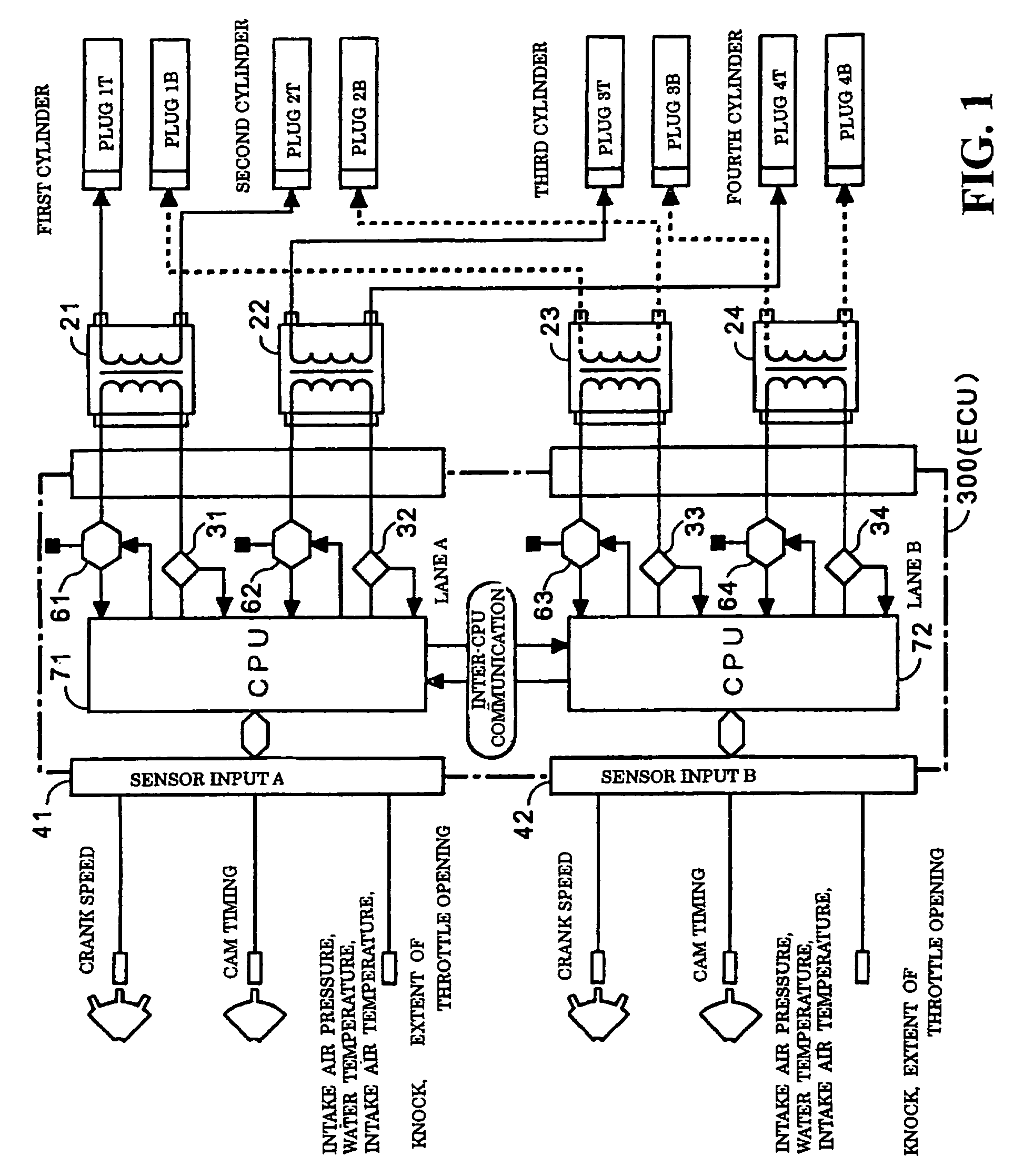
[0039]A detailed description will now be given of preferred embodiments of the present invention with reference to the drawings. FIG. 1 is a block view showing a block view of an ignition control device for use with an aviation engine of the present invention.

[0040]Each cylinder is equipped with main ignition plugs (1T to 4T) and back-up ignition plugs (1B to 4B) for backing these up. Lane A including CPU 71 and lane B including CPU 72 are included at ECU 300 and the ignition control system is multiplexed by these two lanes A, B.

[0041]At lane A, the main ignition plug 1T of the first cylinder and the main ignition plug 2T of the second cylinder are supplied with electricity by the simultaneous ignition type first ignition coil 21. The main ignition plug 3T of the third cylinder and the main ignition plug 4T of the fourth cylinder are supplied with electricity by the simultaneous ignition type second ignition coil 22. The primary sides of each of the ignition coils 21, 22 are connect...


PUM


Abstract

An electronic control device is provided for an aviation engine. Each cylinder of the engine is equipped with main ignition plugs and back-up ignition plugs. Lane A including a first CPU and lane B including a second CPU are included in an ECU. The ignition control system is multiplexed by the two lanes A, B. The first and second CPU independently calculate ignition timing for each cylinder based on each sensor signal, and then exchange the results of these calculations with each other. At each cylinder, ignition timing is synchronized in such a manner that ignition timing of the main ignition plugs and ignition timing of the back-up ignition plugs match. The electronic control device so configured has a high level of redundancy with a small number of CPU's. Thus, electronic control device can be provided for the aviation engine with few limitations placed in relation to installation location.

Description

CROSS-REFERENCE TO RELATED APPLICATION[0001]The present application claims priority under 35 U.S.C. §119 to Japanese Patent Application Ser. No. 2001-284060, filed Sep. 18, 2001, the entire contents of which are hereby incorporated by reference.BACKGROUND OF THE INVENTION[0002]1. Field of the Invention[0003]The present invention relates to an electronic control device for an aviation engine and particularly relates to an electronic control device for an aviation engine for automatically controlling all fuel consumption and ignition timing etc. using a computer.[0004]2. Description of Background Art[0005]FADEC (Full Authority Digital Engine Control) is a generic name for a system for electronically controlling an aviation engine, that receives information regarding the position of a throttle lever operated by a pilot and the engine, together with various information from various sensors fitted to the aviation craft, and controls the engine so as to obtain optimum engine thrust. Engin...

Claims


Application Information

Patent Timeline
Patent Type & Authority Patents(United States)
IPC IPC(8): G06F19/00F02P5/00F02D29/00F02D45/00F02P5/15
CPCF02D41/266F02P5/1518F02P15/02F02P15/08F02D37/02F02D2250/12Y02T10/46F02D2400/08Y02T10/40
Inventor URUNO, HIROSHIHAMAUZU, AKIRAYOKOYAMA, KIYOAKIKITAURA, HIROHISA
Owner HONDA MOTOR CO LTD
Why Eureka
Try Eureka