Composite system, method for its manufacture, and measurement pickup using such a composite system

a composite system and composite technology, applied in the field of composite systems, can solve the problems of inability to remove the zero-point errors attributable to the loss-of-strength phenomena of composite systems, and the inability to manufacture, and achieve the effects of high-strength and lasting, stable, and long-term enduran

Active Publication Date: 2007-11-27
ENDRESS HAUSER FLOWTEC AG
View PDF21 Cites 65 Cited by
  • Summary
  • Abstract
  • Description
  • Claims
  • Application Information

AI Technical Summary

Benefits of technology

[0102]A further advantage of the invention is, among other things, that, in case required, a soldering, brazing or welding process for the affixing of the measuring tube in the measurement pickup can be avoided, since, already by the mixing of mechanical interference locking and frictional locking, a very stable, high-strength and lasting, mechanical connection between the components of the composite system can be achieved, especially also in spite of continuing vibrational loading of the composite system. Corresponding investigations have, for example, shown that, while avoiding supplemental solder, braze or weld connections, alone composite systems of the described kind formed by frictional locking permit direct achievement of pull-out strength increased by a factor of three. A further advantage of the invention is that the cold-forming, affixing methods already described in U.S. Pat. No.-A 5,610,342 or U.S. Pat. No.-A 6,047,457 and subsequently proved in practice can be applied, and, correspondingly, also the already installed press and / or rolling equipment can predominantly continue to be used. Additionally, with use of the aforementioned press or rolling equipment, it becomes, on the one hand, possible, alone by the continued use of machine and tool settings recognized as optimum for the manufacture of conventional composite systems, to achieve a marked improvement of the pull-out strength and, therefore, also of the longterm endurance. Now, on the other hand, in comparison to conventional composite systems with composite systems formed with purely frictionally locked connections, it is also considerably easier to assure that the measuring tube, despite the high clamping forces with which it is held in the support element, itself scarcely experiences any deformation, and, consequently, even after installation, a largely constant, uniform cross section is maintained over the entire length of the measuring tube.
[0103]As a further advantage, especially compared to conventional composite systems formed in part or entirely by means of bonding, must be mentioned the considerable simplification of manufacture and also the lowering of manufacturing costs. Moreover, the required high quality of the composite system, be it with respect to the material properties of the used components or be it with respect to mechanical strength, can not only be increased but, also, be reproduced far more reliably.

Problems solved by technology

Already the slightest departure of the strength of the aforementioned composite systems from the situation existing during calibration can result in significant, no longer manageable, fluctuations of the zero point and, consequently, in practically unusable measurement signals.
Usually, such zero-point errors attributable to loss-of-strength phenomena in the composite systems can only be removed by complicated repair measures performed remote from the pipeline or only by installation of a new, inline, measuring device.
As described in U.S. Pat. No.-A 5,610,342, the heat needed for the mentioned welding, soldering or brazing leaves behind, following cooling, residual stresses at the locations of the joints between the measuring tubes and the end pieces which can lead to stress corrosion cracking, which can, to a greater or lesser degree, weaken the joints and / or the material of the measuring tube.
Beyond this, such oscillatory rubbing can bring about the corrosion of the materials of the composite system in the area of the mutually contacting surfaces.
This can, in turn, mean that the first component and the second component lose, at locations, the mechanical contact brought about by the rolling, pressing or shrinking, due to thermally related expansions, so that the composite system can be weakened to an unallowable degree.
As a result, the pull-out strength of the composite system can sink, so that the desired high zero-point stability of the measurement pickup can also not, without more, be assured with such press-joined assemblies.
However, this can possibly bring up again the above-mentioned problems associated with welded connections.
However, even this composite system can experience a lessening of its nominal pull-out resistance, be it due to oscillatory rubbing and / or thermally-related expansion, especially in the case of use in a measurement pickup with a measuring tube executing, at least at times, bending oscillations.

Method used


Image

  • Composite system, method for its manufacture, and measurement pickup using such a composite system
  • Composite system, method for its manufacture, and measurement pickup using such a composite system
  • Composite system, method for its manufacture, and measurement pickup using such a composite system

Examples


Embodiment Construction

[0112]While the invention is susceptible to various modifications and alternative forms, exemplary embodiments thereof have been shown by way of example in the drawings and will herein be described in detail. It should be understood, however, that there is no intent to limit the invention to the particular forms diclosed, but on the contrary, the intention is to cover all modifications, equivalents, and alternatives falling within the spirit and scope of the invention as defined by the intended claims.

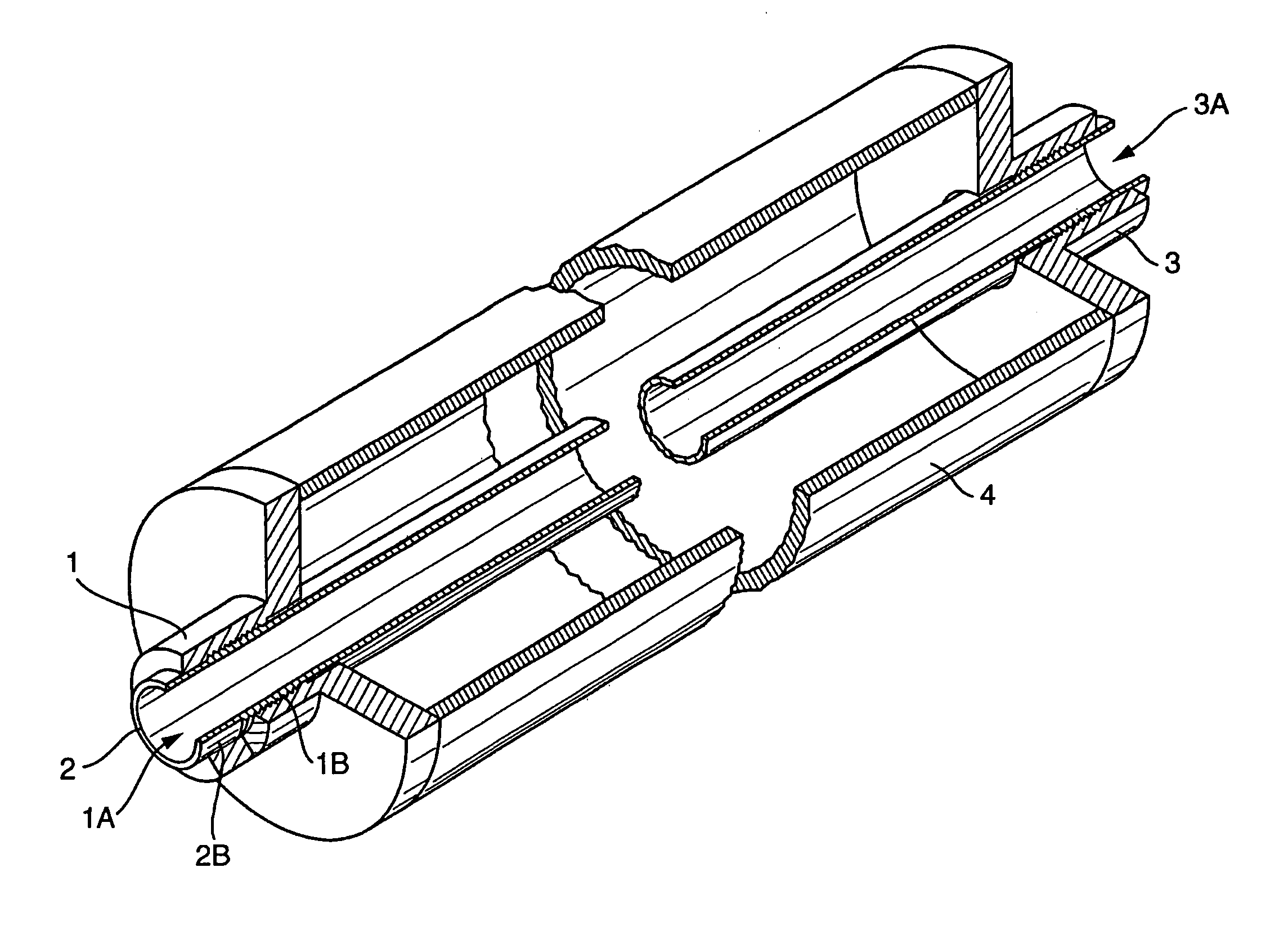
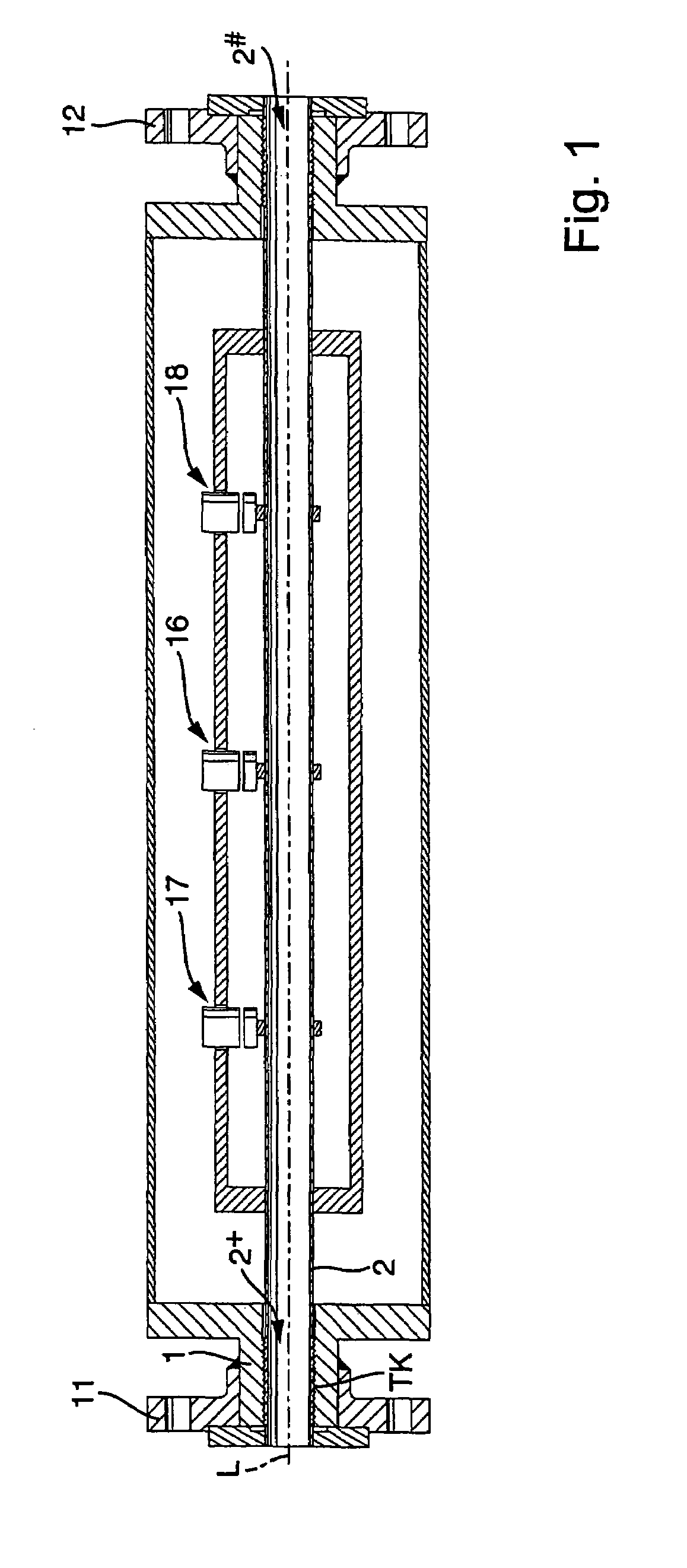
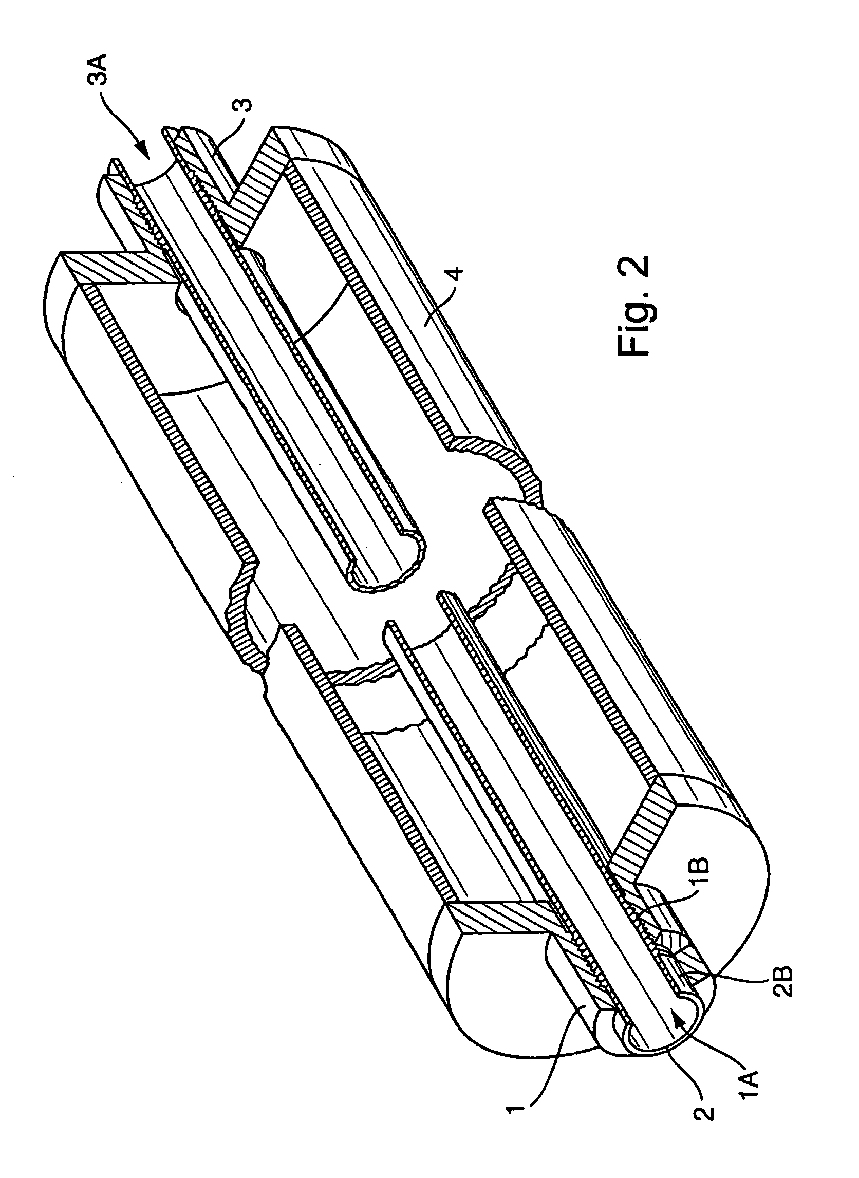
[0113]FIG. 1 shows an example of an embodiment for an, especially bi-metal, composite system formed of a first component 1 and a second component 2 extending at least partially through the first component along an imaginary longitudinal axis L of the composite system. As can be seen in FIG. 2, the second component 2 has, in such case, an at least partially curved, outer surface, especially a cylindrical outer surface, which so contacts an inner surface of the first component flushly, t...


PUM

PropertyMeasurementUnit
temperatureaaaaaaaaaa
depthaaaaaaaaaa

Abstract

A composite system includes a first component, for instance of metal, and a second component extending at least partly through the first component along an imaginary longitudinal axis of the composite system. The second component contacts, with an at least partially curved, especially cylindrical, outer surface, an inner surface of the first component flushly such that the first component at least sectionally, at least partly, grips around the second component. Joining surfaces of the composite system, which are formed by the mutually contacting surfaces of the two components, are formed in such a manner that the two components exhibit contour portions in the area of these joining surfaces embodied as self-closing, peripheral surfaces. The contour portions fit at least partly into one another, to form a mechanical interference locking effective, at least in part, likewise in the direction of the longitudinal axis. Additionally, the second component, with its outer surface, contacts the inner surface of the first component flushly, such that the two components are mechanically tightly connected together also by means of a frictional locking effective at least partly in the direction of the longitudinal axis. Alternatively, or in supplementation thereof, at least one of the components is subjected at least partly to lastingly elastic, especially mixed plastic-elastic, deformations. The composite system is distinguished by a high pull-out strength, even in the presence of repeatedly arising vibrations in one of the components and is, therefore, especially suited also for use in a vibration-type measurement pickup.

Description

FIELD OF THE INVENTION[0001]The application claims the benefit of provisional application No. 60 / 617,642 filed on Oct. 13, 2004.[0002]The invention relates to a composite system involving a first component, especially a first component of metal, and a second component, especially a second component likewise of metal, joined with the first component, especially in the context of a vibration-type measurement pickup having at least one measuring tube which vibrates in operation. Additionally, the invention relates to a method for manufacturing such a composite system, especially for application in a measurement pickup of vibration-type.BACKGROUND OF THE INVENTION[0003]In the technology of industrial measurements and automation, inline measuring devices having a vibration-type measuring pickup are used for high-accuracy registering of measured process variables, especially flow-dynamic and / or rheological, measured variables, of media flowing in conduits, especially pipelines. Such measu...

Claims


Application Information

Patent Timeline
Patent Type & Authority Patents(United States)
IPC IPC(8): G01H11/00G01F15/18
CPCG01F1/8404G01F1/8409G01F1/8413G01F15/185G01N11/16G01F1/849Y10T428/12Y10T428/24149
Inventor LORENZ, RAINER
Owner ENDRESS HAUSER FLOWTEC AG
Why Eureka
Try Eureka