Electrochromic mirrors and other electrooptic devices
a mirror and electrooptic technology, applied in the field of electrooptic devices, can solve the problems of contaminating equipment, limiting back reaction, and increasing the memory of ec devices
- Summary
- Abstract
- Description
- Claims
- Application Information
AI Technical Summary
Benefits of technology
Problems solved by technology
Method used
Image
Examples
example 1
Electrochromic Window Device Durability—UV Stabilizer A
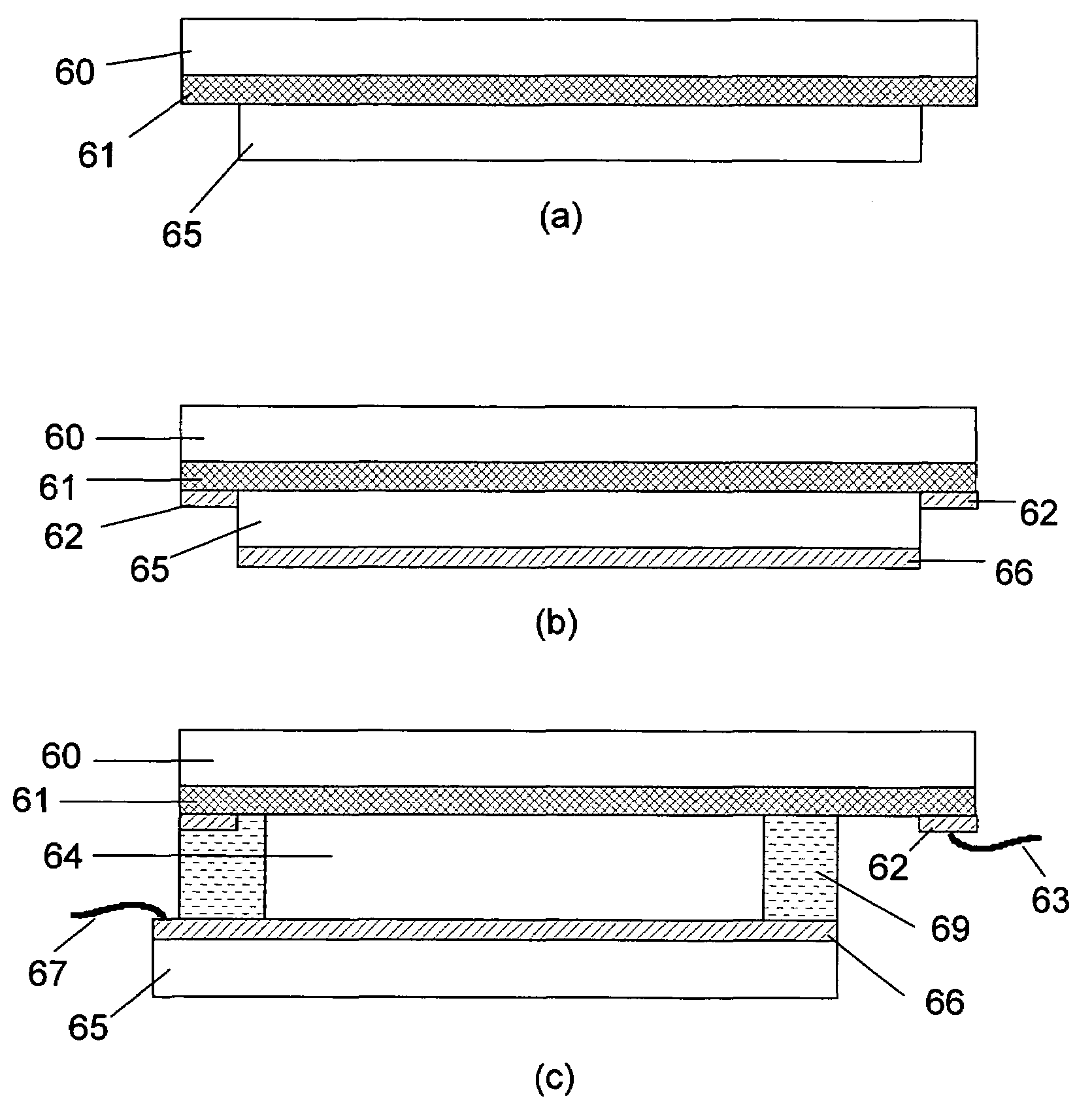
[0139]ITO substrates (15 Ω / sq) were cut into two 5.25″×3.67″ rectangular pieces. The active area of the device was about 92 sq.cm. In one piece, two holes about 3 mm in diameter were drilled near the corners of one of the diagonals to fill the electrolyte. The substrates were then washed, dried and stored in clean room conditions. An epoxy containing 102.5 micron glass bead spacers was dispensed around the edges of one of the substrates and the second substrate was placed on top of it to make a cavity such that the two substrates were staggered by 5 mm along the long side of the rectangular edge. This exposed edge on both substrates was later used to apply a busbar and make electrical connections. The epoxy seal was cured at 150° C. The cavity was filled at room temperature with a liquid electrolyte containing 0.05M diethyl viologen bis(trifluoromethanesulfonyl)imide, 0.05M 5,10 dihydro-5-10-dimethyl phenazine and 2 wt % of 2-4-...
example 2
Electrochromic Window Device Durability—UV Stabilizer B
[0143]Another set of electrochromic cells was prepared as described in Example 1. In this case, the UV stabilizer was substituted with 5 wt % of 2-cyano-3,3 diphenyl-acrylic acid ethyl ester in the same ionic liquid as Example 1. The electrochromic performance of the window device was determined as described in Example 1. These devices colored uniformly to a deep blue color and reversed to the original colorless state upon bleaching. Three devices were subjected to each of the tests as described in example 1. The results are shown in Tables 2a, 2b and 2c. The devices did not show any discoloration after any of the tests or when kept at −40° C.
[0144]
TABLE 2a% T (550 nm)Time (s) for 80% of full rangeBleachedColoredTime to colorTime to bleachInitial86.311.922.450.8After 79,50085.912.122.650.1cycles
[0145]
TABLE 2b% T (550 nm)Time to 80% of full rangeBleachedColoredTime to colorTime to bleachInitial87.111.122.953.9After 1,000 KJ81.610...
example 3
Electrochromic Window Device Durability—Mixed UV Stabilizers
[0147]Another set of Electrochromic windows was prepared as described in Example 1. In this case, the UV stabilizers were 2 wt % of 2-4-dihydrobenzophenone and 5 wt % of 2-cyano-3,3 diphenyl-acrylic acid ethyl ester in the same ionic liquid as Example 1. The electrochromic performance of the window device was determined as described in Example 1. This device colored uniformly to a deep blue color and reversed to the original colorless state upon bleaching. Three devices were subjected to tests as described in Example 1. The results are shown in Tables 3a, 3b and 3c.
[0148]
TABLE 3a% T (550 nm)Time (s) for 80% of full rangeBleachedColoredTime to colorTime to bleachInitial85.111.122.250.3After 79,50085.811.422.346.4cycles
[0149]
TABLE 3b% T (550 nm)Time (s) for 80% of full rangeBleachedColoredTime to colorTime to bleachInitial85.810.822.349.2After 1,000 kJ of78.09.523.556.0UV exposure
[0150]
TABLE 3c% T (550 nm)Time (s) for 80% of ...
PUM
| Property | Measurement | Unit |
|---|---|---|
| size | aaaaa | aaaaa |
| refractive index | aaaaa | aaaaa |
| melting temperature | aaaaa | aaaaa |
Abstract
Description
Claims
Application Information
 - R&D
- Intellectual Property
- Life Sciences
- Materials
- Tech Scout
- Unparalleled Data Quality
- Higher Quality Content
- 60% Fewer Hallucinations
Browse by: Latest US Patents, China's latest patents, Technical Efficacy Thesaurus, Application Domain, Technology Topic, Popular Technical Reports.
© 2025 PatSnap. All rights reserved.Legal|Privacy policy|Modern Slavery Act Transparency Statement|Sitemap|About US| Contact US: help@patsnap.com


