Endovascular cryotreatment catheter

a cryotreatment catheter and endovascular technology, applied in the field of endovascular catheters, can solve the problems of high turbulent flow conditions, limited cooling rate, and constraints on the working devi

Inactive Publication Date: 2007-11-27
MEDTRONIC CRYOCATH LP
View PDF28 Cites 146 Cited by
  • Summary
  • Abstract
  • Description
  • Claims
  • Application Information

AI Technical Summary

Problems solved by technology

The requirement that coolant be localized in its activity poses constraints on a working device.
Furthermore, the rate of cooling is limited by the ability to circulate a sufficient mass flow of coolant through the active contact region.
However, the expansion of a phase change or high pressure coolant exiting from a nozzle within a small catheter tip creates highly turbulent flow conditions.
However, if one were to replace such a tip with an inflatable balloon as is commonly used for angioplasty, the size of the chamber would vary considerably as the balloon is inflated, causing substantial variations in flow conditions of the fluid entering the tip and substantial changes in heat transport across the expanding balloon wall.
Furthermore, coolant materials suitable for high pressure or phase change refrigeration may pose risks when used within a blood vessel.
Another factor which adds complexity to the task of cryocatheter design is that the primary mechanism of treatment involves thermal conduction between the catheter and a targeted region of tissue.
Additionally, the operation of such a device for therapeutic purposes requires that the coolant be contained within the catheter at all times, lest a leak of coolant enter the body and thereby cause significant harm.
These techniques however, lack robustness, in that if the unitary balloon, cooling chamber, or other form of containment develops a crack, leak, rupture, or other critical structural integrity failure, coolant may quickly flow out of the catheter.
Finally, a major challenge for effective cryotreatment is the ability to fine tune the pressure and temperature of the coolant flow at the distal tip of the catheter, so as to controllably apply cooling to adjacent tissue.
Thus, in order to maintain the balloon pressure at safe levels, without exceeding ambient body pressures, the device must be operated at relatively lower balloon pressures, which have the undesired effect of raising the cooling power to levels which are difficult to control and may even harm or damage the target tissue.

Method used


Image

  • Endovascular cryotreatment catheter
  • Endovascular cryotreatment catheter
  • Endovascular cryotreatment catheter

Examples


embodiment 80

[0047]FIG. 4 illustrates another embodiment 80 of the present invention. This embodiment has a multi-balloon structure and a cooling segment 84 at the catheter tip. As illustrated, segment 84 corresponds to the expansion chamber or region of greatest cooling activity of the catheter and includes a cooling pattern assembly. This may be a spiral metal wrapping that provides stiffness, form and thermal conductivity to the segment. A first balloon 82 is positioned on one side of the cooling segment 84 to serve as an anchor and blood vessel occluder or flow blocker, and in this embodiment a second balloon 86 extends from the other end of the cooling segment. As shown, the first balloon is substantially ovaloid and symmetrical, while the second balloon 86 has a tapered, trumpet-or bell-shaped aspect that allows it to wedge at the end of a vessel, for example, in the ostium or junction of the vessel end to an organ. Thus, while the balloon 82 is inflatable within a vessel to serve as an an...

embodiment 400

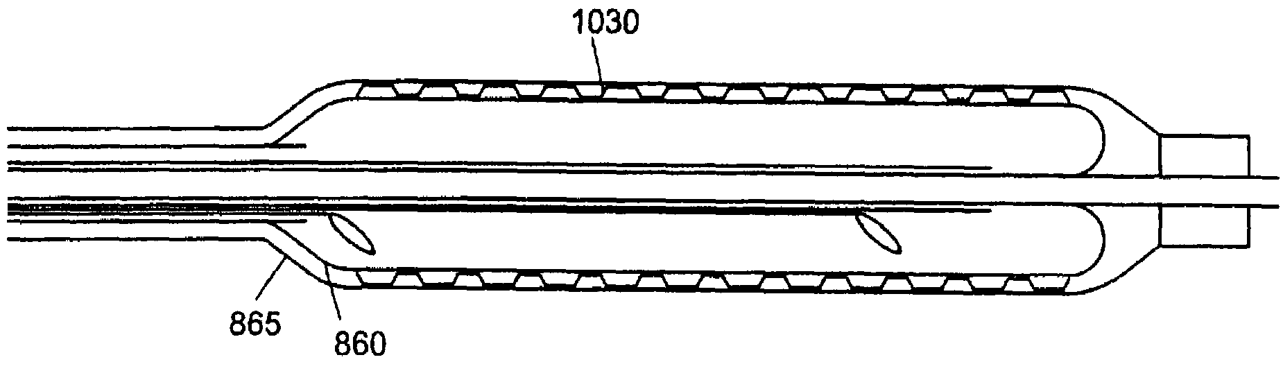
[0065]The illustrated embodiment of FIG. 10A has a generally continuous balloon contour in which at least a portion of the end segments 312a, 312b inflates to the diameter of the surrounding blood vessel or tissue lumen and serves to displace blood, fluid or tissue away from the cryogenic treatment portion at the center of the catheter tip. As shown in FIG. 10B, this has the effect of creating a cooling region that forms a relatively symmetrical ice ball volume (indicated by dashed lines in the Figure) around the vessel and catheter tip, with greater depth of penetration centered directly over the cryogenic chamber and with cooling damage tapering off away from that region. The balloon need not be a single continuous or partitioned balloon but may be implemented with separate balloons that in turn may be inflated via separate filler or inflation tubes (not illustrated) so as to more effectively achieve or more independently initiate the blocking and heat isolation functions. FIG. 10...

embodiment 700

[0071]FIG. 12B illustrates another embodiment 700 of a cryogenic delivery catheter of the invention. This embodiment again has the basic structure of a cooling chamber 703 in a distal cooling tip 710 fed by a coolant supply lumen 701. However, in this embodiment an additional fluid delivery line 725 extends through the catheter body and is mounted to deliver fluid F externally of the tip 710 into the space between the cooling chamber exterior wall and the surrounding tissue. The delivery line 725 may have one or more outlets positioned to provide fluid F in defined locations. As illustrated in phantom by element 715, a perforated membrane or other external distribution structure may also be provided to disperse or spread the fluid F exiting the delivery line 725. In general, the delivery line 725 may deliver a therapeutic treatment liquid, or simply a heat conduction fluid to cryochamber surface. Applicant contemplates generally that during cryotreatment, the fluid F will freeze in ...


PUM


Abstract

An elongated catheter device with a distal balloon assembly is adapted for endovascular insertion. Coolant injected through the device may, in different embodiments, directly cool tissue contacting the balloon, or may cool a separate internal chamber. In the first case, the coolant also inflates the balloon, and spent coolant is returned to the handle via a return passage extending through the body of the catheter. Plural balloons may be provided, wherein a secondary outer balloon surrounds a primary inner balloon, the primary balloon being filled with coolant and acting as the cooling chamber, the secondary balloon being coupled to a vacuum return lumen to serve as a robust leak containment device and thermal insulator around the cooling chamber. Various configurations, such as surface modification of the balloon interface, or placement of particles, coatings, or expandable meshes or coils in the balloon interface, may be employed to achieve this function.

Description

CROSS-REFERENCE TO RELATED APPLICATION[0001]This application is a continuation of U.S. patent application Ser. No. 09 / 945,319, filed Aug. 31, 2001, by Miriam Lane, et al, entitled ENDOVASCULAR CRYOTREATMENT CATHETER, now issued U.S. Pat. No. 6,575,966, which application is a Continuation-in-Part of U.S. patent application Ser. No. 09 / 378,972, filed Aug. 23, 1999, now issued U.S. Pat. No. 6,283,959, all of which are incorporated herein by reference.STATEMENT REGARDING FEDERALLY SPONSORED RESEARCH OR DEVELOPMENTn / aFIELD OF THE INVENTION[0002]The present invention relates to endovascular catheters, and in particular, to catheters for cryotreatment of tissue.BACKGROUND OF THE INVENTION[0003]The present invention relates to endovascular cryocatheters, such as angioplasty balloons having a freezing function for treating tissue by extreme cooling contact. These catheters have an elongated body through which a cooling fluid circulates to a tip portion which is adapted to contact and cool ti...

Claims


Application Information

Patent Timeline
Patent Type & Authority Patents(United States)
IPC IPC(8): A61B18/18A61B17/22A61B18/00A61B18/02A61F2/958
CPCA61B18/02A61B2017/22001A61B2017/22051A61B2017/22054A61B2018/0268A61B2018/0022A61B2018/0212A61B2018/0262A61B2017/22069
Inventor LANE, MIRIAMCAPUANO, LEONILDAHOLTAN, DAVIDLALONDE, JEAN-PIERRELUCKGE, CLAUDIAPAGEARD, JEAN-LUCABBOUD, MARWANASMAR, JOHNNY ALBENRABAH, ABDERRAHIMCHEN, KENLEHMANN, JOHN W.MARCHAND, PHILIPPEMARTIN, ROBERTMILDER, FREDRIC L.NAHON, DANIEL
Owner MEDTRONIC CRYOCATH LP
Why Eureka
Try Eureka