
High voltage pulsed power supply using solid state switches

a technology of solid state switches and power supplies, which is applied in the direction of pulse generators, pulse techniques, instruments, etc., can solve the problems of stray capacitance, section may experience higher voltage, and the number of sections that can be stacked together is effectively limited, so as to reduce the fall time of the pulse and reduce the stray capacitance. , the effect of reducing the stray capacitan

Active Publication Date: 2007-11-27
STANGENES IND INC
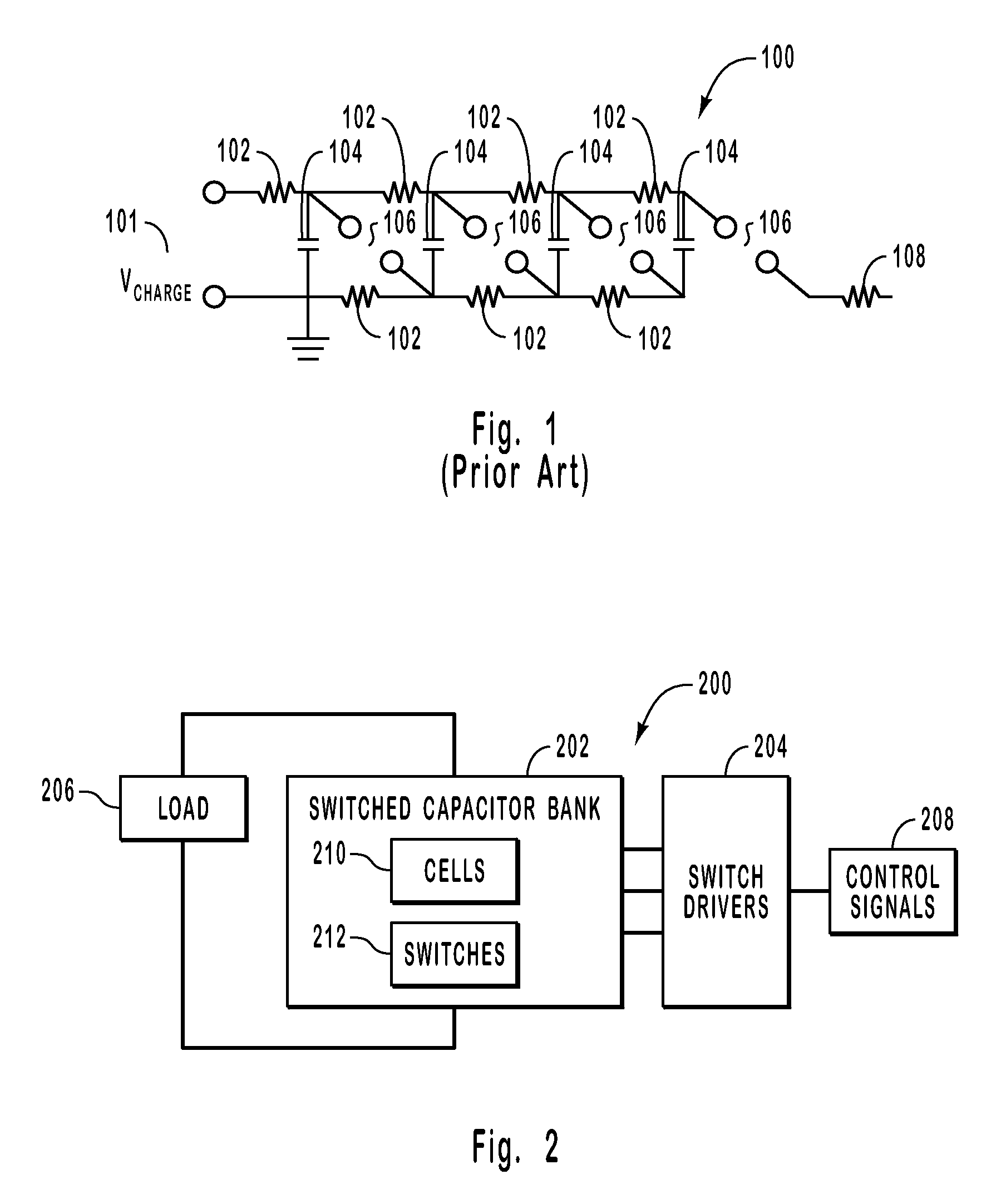
View PDF23 Cites 98 Cited by
  • Summary
  • Abstract
  • Description
  • Claims
  • Application Information

AI Technical Summary

Benefits of technology

This approach reduces stray capacitance, increases the number of stackable sections, decreases size and cost, enhances reliability, and allows for precise control of high voltage pulses without the need for oil, while maintaining functionality even if individual cells fail.

Problems solved by technology

However, it has been found that the number of sections that can be stacked together is effectively limited by stray capacitance.
The stray capacitance also has an adverse affect on the rise time and / or fall times of the voltage pulse.
Because the stray capacitance is not balanced across the sections of the pulse generator, some of the sections may experience higher voltages and may therefore malfunction.
Although most systems are affected by stray capacitance, the inductors, resistors, transformers, and isolated supplied needed to charge the capacitors in the pulse generator also add stray capacitance to the pulse generator.
In other words, the components of conventional pulse generators introduce additional stray capacitance to the system and further reduce the number of sections that can be successfully connected together.
Because Marx Generators are often used to generate high voltages, they can be quite large in both size and weight.
Oil is typically necessary, but is often undesirable.
Conventional pulsed power supplies or Marx Generators are often large and expensive, are limited by stray capacitance, and use components (such as thyratrons) that reduce their reliability.

Method used


Image

  • High voltage pulsed power supply using solid state switches
  • High voltage pulsed power supply using solid state switches
  • High voltage pulsed power supply using solid state switches

Examples


Embodiment Construction

[0027]The present invention relates to systems and methods for generating a voltage pulse. Embodiments of the invention can control an amplitude of the voltage pulse, a duration or width of the voltage pulse, a rise time of the voltage pulse, a fall time of the voltage pulse, and the like or any combination thereof.

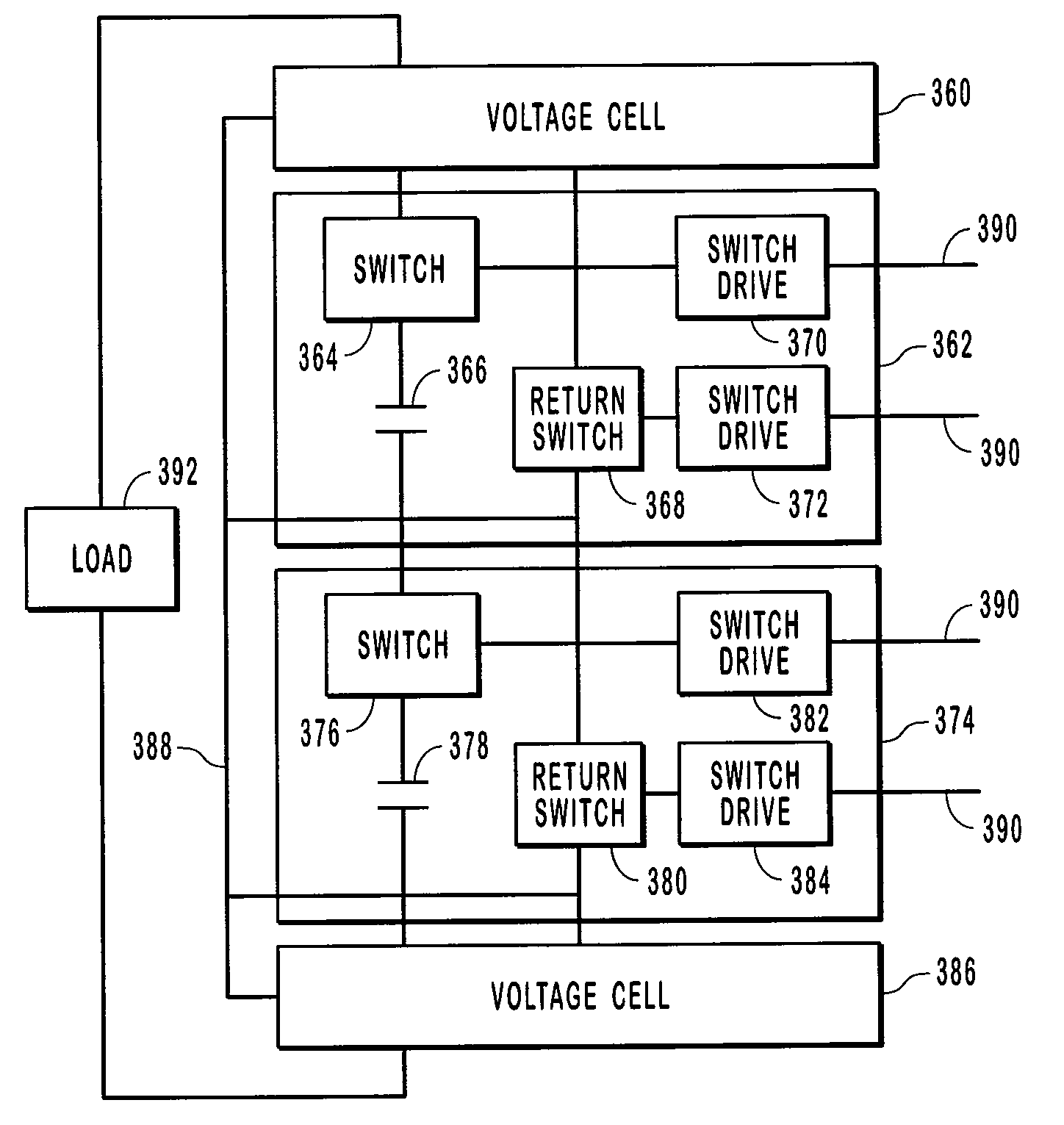
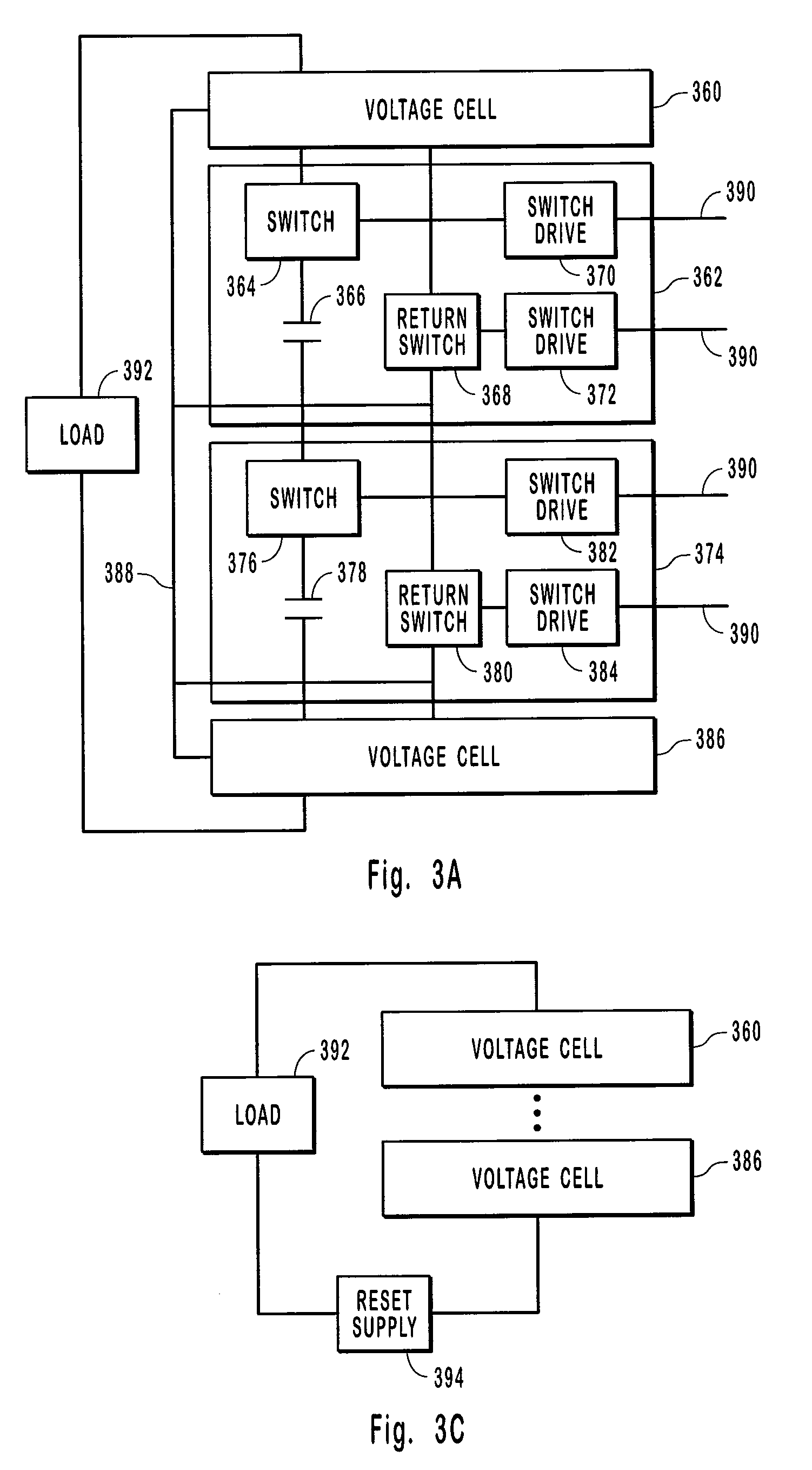
[0028]Embodiments of the invention include voltage cells that typically have both a capacitor and a switch in series. The first and last voltage cells in a series of voltage cells may be adapted to connect to the load. Return switches are also included in most voltage cells. The return switches provide a path for the charging current supplied through a diode chain or a diode chain supply line. Advantageously, the return switches eliminate the use of inductors, resistors, and isolated supplies prevalent in conventional pulse generators. The switch drives are also provided with energy through an auxiliary diode chain, thereby eliminating the need for inductors, resistors, i...


PUM


Abstract

Systems and methods for generating a high voltage pulse. A series of voltage cells are connected such that charging capacitors can be charged in parallel and discharged in series. Each cell includes a main switch and a return switch. When the main switches are turned on, the capacitors in the cells are in series and discharge. When the main switches are turned off and the return switches are turned on, the capacitors charge in parallel. One or more of the cells can be inactive without preventing a pulse from being generated. The amplitude, duration, rise time, and fall time can be controlled with the voltage cells. Each voltage cell also includes a balance network to match the stray capacitance seen by each voltage cell.

Description

CROSS-REFERENCE TO RELATED APPLICATIONS[0001]Not Applicable.BACKGROUND OF THE INVENTION[0002]1. The Field of the Invention[0003]The present invention relates to systems and methods for generating high voltage pulses. More particularly, the present invention relates to systems and methods for generating high voltage pulses controlled by solid state switches.[0004]2. Background and Relevant Art[0005]Many applications need a pulsed power supply that is able to deliver high voltage pulses. Spectrometers, accelerators, radar transmitters, high impedance electron guns, ion tubes, liquid polarizing cells, etc., are examples of applications that need high voltage pulses. In conventional systems, a pulsed power supply uses a high voltage pulse forming network and some sort of switch such as a spark gap or a thyratron.[0006]These types of pulsed power supplies are often created using principles of Marx Generators. Generally, a Marx Generator is circuitry that generates a voltage pulse by char...

Claims


Application Information

Patent Timeline
Patent Type & Authority Patents(United States)
IPC IPC(8): H03K3/64H02M3/18H02M3/07
CPCH02M3/07H03K3/57H02M3/18H02M3/16
Inventor CASSEL, RICHARD L.
Owner STANGENES IND INC
Learn More