Brushless starter-generator with independently controllable exciter field

a starter generator and independent control technology, applied in the direction of electric generator control, dynamo-electric converter control, synchronous motor control, etc., can solve the problems of frequency control, relative complexity and heavy power electronics circuit, increase overall complexity, cost, maintenance,

Inactive Publication Date: 2007-11-27
HONEYWELL INT INC
View PDF31 Cites 29 Cited by
  • Summary
  • Abstract
  • Description
  • Claims
  • Application Information

AI Technical Summary

Problems solved by technology

Current starter-generators typically include relatively complex and heavy power electronics circuits in the control device.
For example, some control devices may include inverters, for converting DC to AC power, rectifiers, for converting AC power to DC power, and potentially complex voltage and frequency control circuits, which can increase overall complexity, cost, and maintenance.
Although brush-type DC machines may alleviate the need for some of these complex and heavy electronic circuits, these also suffer certain drawbacks.
For example, the brushes tend to wear fairly quickly, which can reduce machine reliability and increase the need for periodic maintenance and cleaning.
Some brush-type DC machines can also suffer what is known as torque ripple during startup.
In some instances, the torque ripple can be large, which can result in poor starter performance.

Method used


Image

  • Brushless starter-generator with independently controllable exciter field
  • Brushless starter-generator with independently controllable exciter field
  • Brushless starter-generator with independently controllable exciter field

Examples


Embodiment Construction

[0017]The following detailed description of the invention is merely exemplary in nature and is not intended to limit the invention or the application and uses of the invention. Furthermore, there is no intention to be bound by any theory presented in the preceding background of the invention or the following detailed description of the invention. In this regard, although the starter-generator is described herein as being used with, for example, an aircraft gas turbine engine, it will be appreciated that may be used as a starter-generator with gas turbine engines in numerous other environments included, for example, space, marine, land, or other vehicle-related applications where gas turbine engines are used.

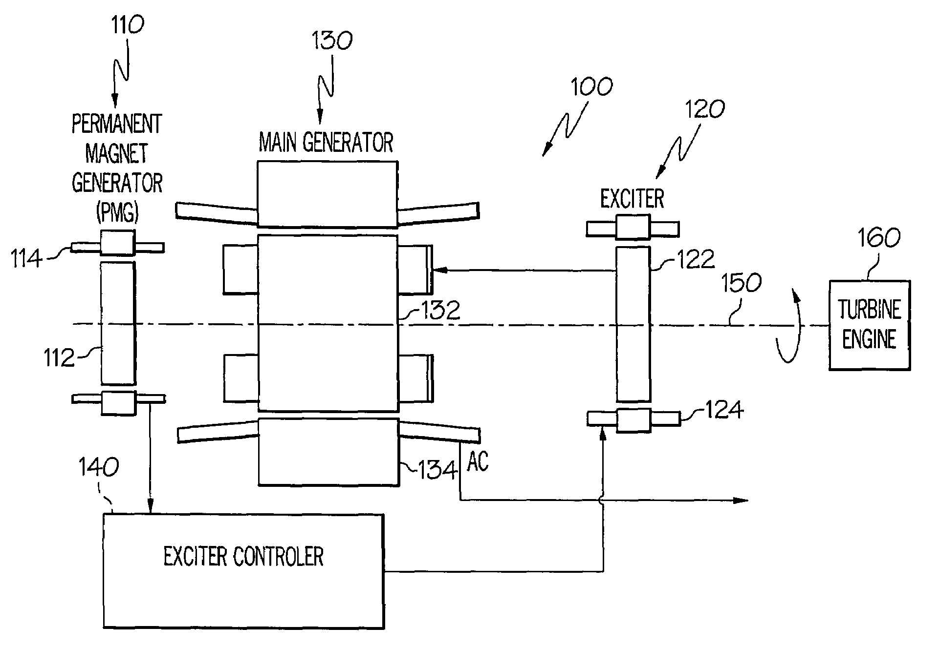
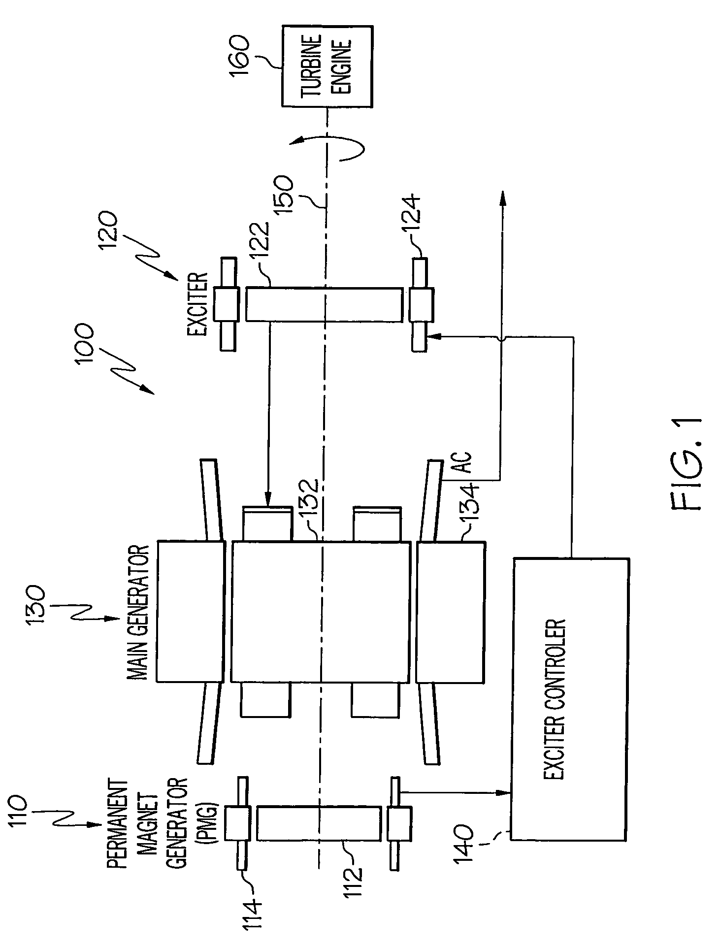
[0018]Turning now to the description and with reference first to FIG. 1, a functional schematic block diagram of an exemplary starter-generator system 100 for use with, for example, an aircraft gas turbine engine, is shown. This exemplary starter-generator system 100 includes a p...


PUM


Abstract

A starter-generator system supplies a controllable torque to a gas turbine engine, to thereby assist in starting the gas turbine engine, by independently controlling excitation frequency and / or voltage magnitude. The starter-generator includes a multi-phase exciter stator, a rotationally mounted multi-phase exciter rotor, a multi-phase main stator, a rotationally mounted multi-phase main rotor, and an exciter controller. The rotationally mounted multi-phase exciter rotor has a plurality of exciter rotor windings wound thereon that, upon excitation thereof with a rotating electromagnetic exciter flux generated by the exciter stator, have non-rectified excitation currents induced therein. The rotationally mounted multi-phase main rotor has a plurality of main rotor windings wound thereon that are electrically connected to receive the non-rectified excitation currents induced in the exciter rotor windings and that, upon excitation thereof with a rotating electromagnetic flux and in response to the non-rectified excitation currents supplied thereto, have currents induced therein that generate a main rotor torque to thereby cause the multi-phase main rotor and the multi-phase exciter rotor to rotate. The exciter controller is electrically coupled to at least the exciter stator and is configured to selectively supply the electrical excitation thereto, to thereby selectively control the generated main rotor torque.

Description

TECHNICAL FIELD[0001]The present invention relates to rotating electrical machines such as starter-generators for gas turbine engines and, more particularly, to a brushless starter-generator with an independently controllable exciter field.BACKGROUND[0002]An aircraft may include various types of rotating electrical machines such as, for example, generators, motors, and motor / generators. Motor / generators are used as starter-generators in some aircraft, since this type of rotating electrical machine may be operated in both a motor mode and a generator mode. A starter-generator may be used to start the engines or auxiliary power unit (APU) of an aircraft when operating as a motor, and to supply electrical power to the aircraft power distribution system when operating as a generator. Thus, when operating as a motor, a starter-generator may be used to start the engines.[0003]One particular type of aircraft starter-generator includes three separate brushless generators, namely, a permanen...

Claims


Application Information

Patent Timeline
Patent Type & Authority Patents(United States)
IPC IPC(8): H02P9/44
CPCH02K19/28H02K19/12
Inventor XU, MINGZHOUBENSON, DWAYNE M.
Owner HONEYWELL INT INC
Why Eureka
Try Eureka