Display element and display device

a technology of display element and display device, which is applied in the field of display elements, can solve the problems of shortening the display life, reducing the light emission efficiency of organic el elements, and emitted luminance reduction, so as to reduce the numerical aperture, prolong the display life, and compensate the temporal luminance deterioration of electro-optical elements.

Active Publication Date: 2007-11-27
SHARP KK
View PDF6 Cites 2 Cited by
  • Summary
  • Abstract
  • Description
  • Claims
  • Application Information

AI Technical Summary

Benefits of technology

[0021]It is thus an object of the present invention to provide a display element and a display device with which the temporal luminance deterioration of the electro-optical element can be compensated and the display lifetime can be prolonged, without inserting a resistance element in series as described above, and without lowering the numerical aperture by increasing the number of TFTs within the display element and drastically changing the layout of the display element.
[0034]With the present invention as described above, the conductive resistance of the current control element is set such that the ratio β(=Vr / Vel) of a voltage Vr applied across the current control element to a voltage Vel applied across the electro-optical element when the electro-optical element is emitting light satisfies 0.1≦β≦7.0. Thus, the speed of change over time of the luminance of the electro-optical element can be slowed down and the display lifetime of the electro-optical element can be prolonged, without inserting a new resistance element, and without including special compensation circuitry as used in display elements and display devices with the constant current control method.

Problems solved by technology

However, ordinary organic EL elements have the characteristic that their emitted luminance for a given current decreases over time (due to deterioration of the element), so that also with the constant current control method, a decrease in emitted luminance occurs over the course of time.
However, it is well known that when the luminance of the organic EL element is stepped up, then the deterioration of the organic EL element occurs even earlier, thus shortening the display lifetime.
Moreover, the light emission efficiency of the organic EL element is reduced, and also the power consumption of the organic EL element is relatively increased, so that also in view of the display characteristics, it is not preferable to step up the luminance of the organic EL element.
It should be noted that the explanations here relate to an organic EL element as an example of an electro-optical element, but there is no limitation to organic EL elements, and similar problems occur also with other light emitting elements in which the light emission amount of the element is controlled in accordance with the current amount flowing through the element.

Method used


Image

  • Display element and display device
  • Display element and display device
  • Display element and display device

Examples


Embodiment Construction

[0052]The following is a description of embodiments of the present invention, with reference to the accompanying drawings.

1. General Principles

[0053]Before describing configurations of embodiments of the present invention, the following is a description of the principles to be applied with the present invention and the effects that can be obtained.

[0054]It is known that the deterioration of the element characteristics over the course of time ordinarily can be described by an exponential function. Thus, in the following description, the temporal change of the normalized luminance of a single electro-optical element is approximated by an exponential function L(t). This exponential function L(t) is given by:

L(t)=exp(−K·t)  (1)

where K represents an exponential coefficient and t represents time.

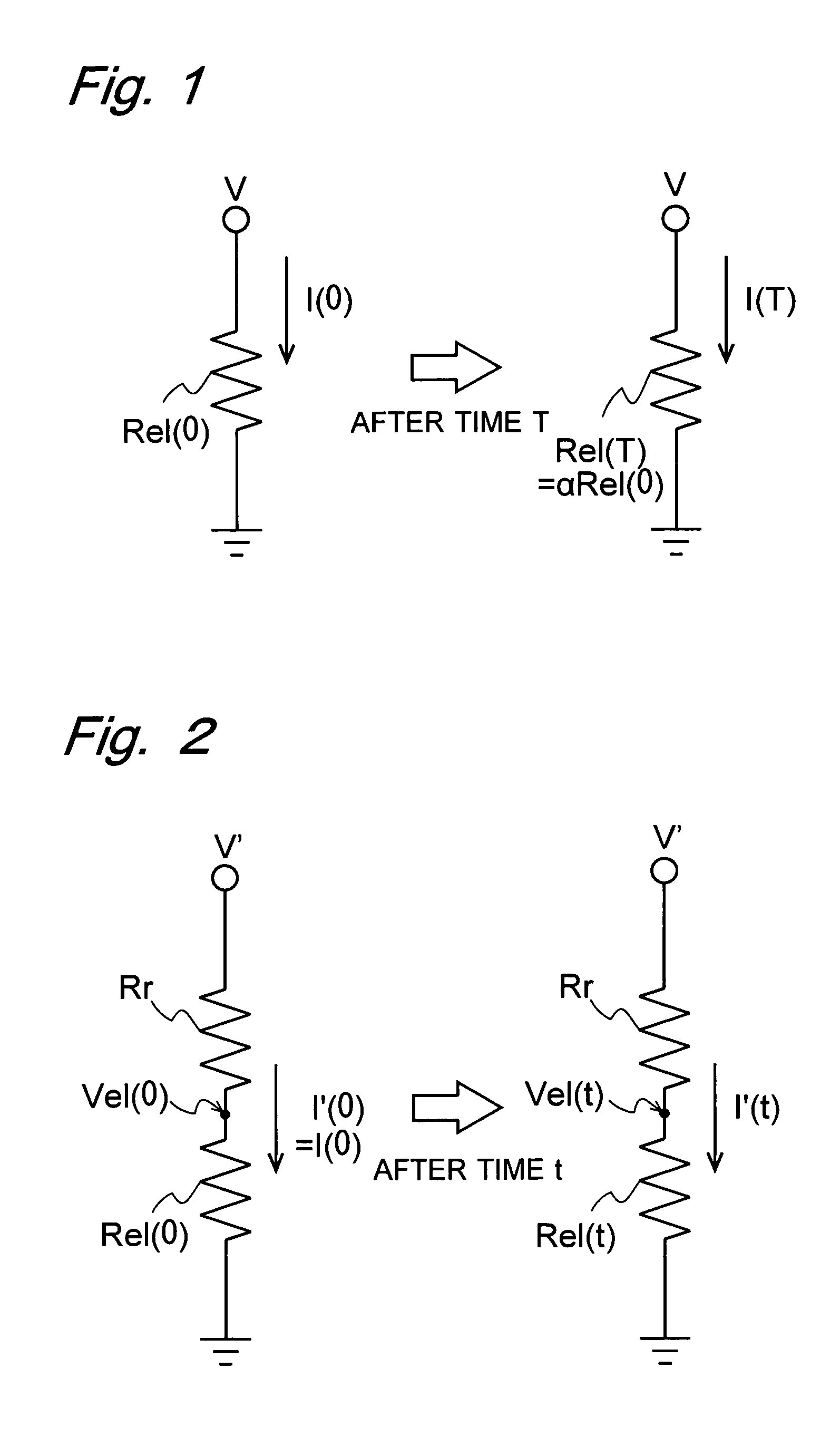
[0055]FIG. 1 is a circuit diagram of a single electro-optical element emitting light. When V is the voltage applied by the power source to the electro-optical element in the figure, Rel(0) is the ...


PUM


Abstract

A display element is configured as follows in order to prolong the display lifetime of an electro-optical element without inserting a resistance element or lowering the numerical aperture due to a change in layout. The display element includes an organic EL element, which is an electro-optical element, a power source line electrode, a scanning signal line electrode, a data signal line electrode, a common electrode, an auxiliary capacitance, a current control TFT for controlling the current flowing through the organic EL element, and a data voltage control TFT for controlling the timing at which current flows through the organic EL element. The conductive resistance of the current control TFT is set such that 0.1≦β≦7.0, where β(=Vr / Vel) is a ratio of a voltage Vr applied across the current control TFT to a voltage Vel applied across the organic EL element. Thus, the speed of the temporal change of the luminance of the organic EL element is slowed down, and the display lifetime is prolonged.

Description

BACKGROUND OF THE INVENTION[0001]1. Field of the Invention[0002]The present invention relates to display elements in which light emission is controlled by the amount of current flowing through an electro-optical element, as well as to display devices including such display elements.[0003]2. Description of the Related Art[0004]Conventionally, there are display elements using, as electro-optical elements, elements whose light emission amount is controlled by the amount of current flowing through the elements, for example LEDs (light emitting diodes) for which inorganic EL (electroluminescent) elements and organic EL elements are typical examples. In this specification, “electro-optical elements” mean any elements whose optical characteristics are changed by applying electricity, such as not only the aforementioned organic EL elements etc., but also FEDs (field emission displays), charge-driven elements, liquid crystals, E-ink (electronic ink) and the like. It should be noted that in t...

Claims


Application Information

Patent Timeline
Patent Type & Authority Patents(United States)
IPC IPC(8): G09G3/30H01L51/50G09F9/30G09G3/20G09G3/22G09G3/32H01L27/12H01L27/32
CPCG09G3/3233H01L27/12G09G2300/0417H01L27/3244G09G2320/043G09G2300/0842H10K59/12
Inventor MUROI, TAKAOSENDA, TAKAHIRO
Owner SHARP KK
Why Eureka
Try Eureka