Exposure method, condensing lens and exposure machine

A technology of condensing lens and exposure method, which is applied in the fields of optomechanical equipment, microlithography exposure equipment, photolithography process exposure device, etc., can solve the problems of difficult imaging of glass substrates, small depth of focus, etc., and increase the stability of mass production. , reduce the numerical aperture, optimize the effect of the exposed image

Inactive Publication Date: 2017-10-13
WUHAN CHINA STAR OPTOELECTRONICS TECH CO LTD
View PDF6 Cites 0 Cited by
  • Summary
  • Abstract
  • Description
  • Claims
  • Application Information

AI Technical Summary

Problems solved by technology

[0008] In order to solve the technical problem in the above-mentioned prior art that the depth of focus is small and the imaging on the glass substrate is difficult, the present invention provides an exposure method, a condenser lens and an exposure machine. The specific scheme is as follows:

Method used


Image

  • Exposure method, condensing lens and exposure machine
  • Exposure method, condensing lens and exposure machine
  • Exposure method, condensing lens and exposure machine

Examples


Embodiment Construction

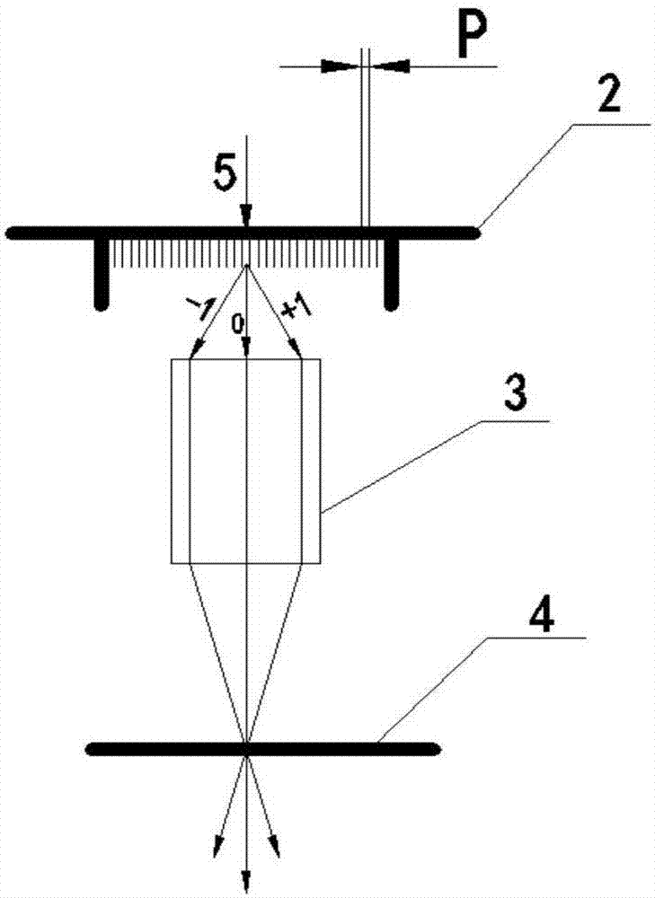
[0038] The present invention will be further described below in conjunction with the accompanying drawings.

[0039] The present embodiment provides an exposure method to improve the imaging depth of focus, and the imaging depth of focus is closely related to the numerical aperture of the condenser lens, and its mathematical relationship is as follows:

[0040]

[0041] In formula (2), DOF is imaging depth of focus; k 2 λ is the process factor; λ is the wavelength of light; NA is the numerical aperture.

[0042] Usually process factor k 2 and the light wavelength λ are constants. It can be seen from formula (2) that when the numerical aperture NA decreases, the imaging depth of focus DOF ​​will increase. The production process of the TFT exposure part is that after the glass substrate is coated with photoresist, it is dried under reduced pressure to remove most of the solvent in the photoresist. Define the graphics; finally display the graphics through the development pr...


PUM


Abstract

The invention provides an exposure method, a condensing lens and an exposure machine. A light blocking device is added to the condensing lens, and the light blocking device is adjusted to reduce the numerical aperture of the condensing lens, so that the imaging focal depth of the exposure machine is improved, then more optimized exposure images are obtained, and the yield stability of products is improved.

Description

technical field [0001] The invention belongs to the field of displays, and in particular relates to an exposure method, a condenser lens and an exposure machine. Background technique [0002] LTPS-TFT LCD (Low Temperature Polysilicon - Thin Film Transistor Liquid Crystal Display; where LTPS, LowTemperature poly-silicon, low temperature polysilicon; TFT, Thin film transistor, thin film transistor; LCD, Liquid Crystal Display, liquid crystal display) has high resolution, responsive The advantages of fast speed, high brightness, high aperture ratio, etc., and because the silicon crystal arrangement of LTPS-TFT LCD is more orderly than that of amorphous silicon (a-Si), the electron mobility is relatively higher than 100 times, and the peripheral drive circuit can be integrated At the same time, it is fabricated on a glass substrate to achieve the goal of system integration, save space and cost of the driver IC. [0003] The LTPS screen is manufactured by adding laser processing...

Claims


Application Information

Patent Timeline
IPC IPC(8): G03F7/20G02F1/13
CPCG03F7/7015G02F1/1303G03F7/70091
Inventor 齐鹏博
Owner WUHAN CHINA STAR OPTOELECTRONICS TECH CO LTD
Why Eureka
Try Eureka