Thermally Induced Ultra-Large Mode Field Fiber

A super-large, mode field technology, applied in the field of lasers, can solve the problems of limited reduction of core numerical aperture, increase of fiber core diameter, and difficulty in manufacturing, and achieve the goal of reducing manufacturing difficulty, reducing numerical aperture, and improving refractive index benchmarks. Effect

Active Publication Date: 2019-04-16
NAT UNIV OF DEFENSE TECH
View PDF11 Cites 0 Cited by
  • Summary
  • Abstract
  • Description
  • Claims
  • Application Information

AI Technical Summary

Problems solved by technology

[0004] The technical problem to be solved by the present invention is to solve the problem that the reduction of the numerical aperture of the fiber core is limited in the first solution, and increase the core diameter of the optical fiber without introducing microstructures, so as to solve the problem caused by the introduction of microstructures in the second solution. The problem of difficulty in production caused by the structure

Method used


Image

  • Thermally Induced Ultra-Large Mode Field Fiber
  • Thermally Induced Ultra-Large Mode Field Fiber
  • Thermally Induced Ultra-Large Mode Field Fiber

Examples


Embodiment 1

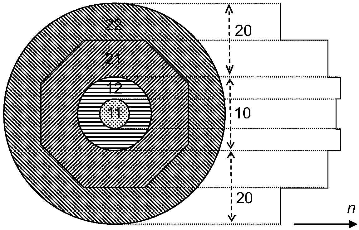
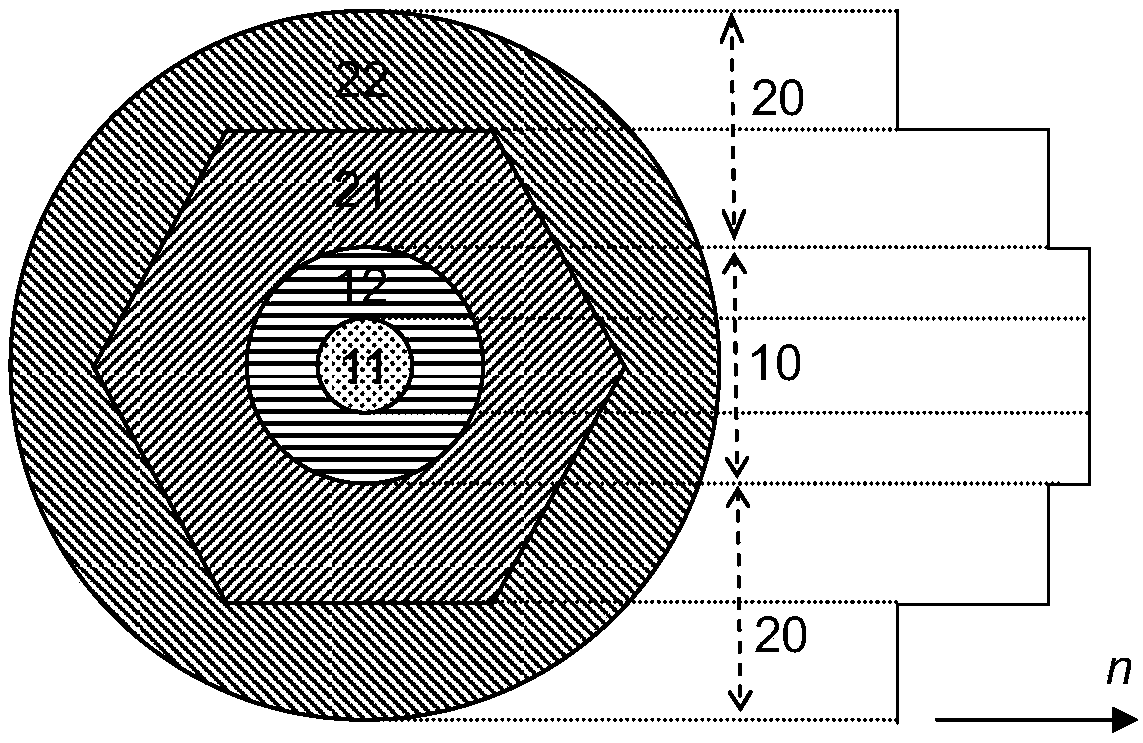
[0025] image 3 An embodiment of the present invention is given (corresponding to the 37th embodiment in Table 1), the arrow indicates the positive direction of the refractive index n, and the solid line on the right indicates the distribution of the refractive index. The inner fiber core 11 that this embodiment selects has a diameter of 30 microns, and the gain medium doped in the inner fiber core 11 is erbium ion and ytterbium ion, and the diameter of the outer fiber core 12 is 150 microns, and the refractive index of the outer fiber core 12 is the same as that of the inner fiber core. The refractive indices of the cores 11 are equal. The inner cladding 21 adopts a regular hexagonal structure, and the diameter of the inscribed circle is 400 microns, and the numerical aperture of the outer core 12 relative to the inner cladding 21 is 0.1. The outer cladding layer 22 is circular, and the numerical aperture of the inner cladding layer 21 relative to the outer cladding layer 22...

Embodiment 2

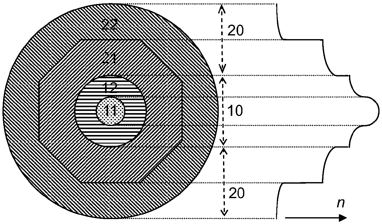
[0028] Figure 4 Another embodiment of the present invention (corresponding to the 527th embodiment of Table 1) is provided. The diameter of the inner fiber core 11 selected in this embodiment is 50 microns, and the gain medium doped in the inner fiber core 11 is ytterbium ions. The diameter of the outer core 12 is 125 microns, and the refractive index of the outer core 12 is smaller than that of the inner core 11, and the difference between the two is 0.00005. The inner cladding 21 adopts a regular octagonal structure, and the diameter of the inscribed circle is 250 microns, and the numerical aperture of the inner cladding 21 relative to the outer core 12 is 0.15. A multimode optical fiber 23 is included in the outer cladding 22 . The multimode optical fiber 23 has a circular core with a diameter of 250 microns and is in optical contact with the inner cladding 21 . The outer cladding layer 22 is circular, and the numerical aperture of the inner cladding layer 21 relative to ...


PUM

PropertyMeasurementUnit
diameteraaaaaaaaaa
diameteraaaaaaaaaa
diameteraaaaaaaaaa

Abstract

The invention discloses a thermotropic ultra-large mode field fiber, and aims to solve the problem of reduced and limited numerical value and aperture of a fiber core and big manufacturing difficulty. The thermotropic ultra-large mode field fiber is composed of the fiber core and a coating layer; the refractive index of the fiber core material is increased along with the temperature increase, and the fiber core includes an inner fiber core and an outer fiber core, and the inner fiber core is located at the center of the outer fiber core, the refractive index of the inner fiber core is less than or equal to the refractive index of the outer fiber core; a gain medium is mixed in the inner fiber core, and the outer fiber core excludes gain medium; the diameter of the inner fiber core is more than or equal to 20 microns, the ratio between the diameter of the inner fiber core and the diameter of the outer fiber core is less than or equal to 50%; the coating layer excludes the gain medium, and includes an inner coating layer and an outer coating layer; the outer coating layer coats the inner coating layer, and the inner coating layer coats the outer fiber core; the refractive index of the inner coating layer is less than that of the outer fiber core; the refractive index of the outer coating layer is less than the refractive index of the inner coating layer. The numerical value and aperture of the inner fiber core are further reduced, the manufacturing difficulty is lowered, and the light filtering pressure of the coating layer is released.

Description

technical field [0001] The invention relates to the technical field of lasers. In particular, it relates to an active optical fiber that realizes a waveguide structure based on thermal effects, can realize ultra-large mode field laser output, and has a simple manufacturing process. Background technique [0002] Fiber laser has the characteristics of light weight, compact structure, long life, good beam quality, strong anti-interference ability, etc. It has a wide range of applications in the fields of communication, sensing, machining, medical treatment, scientific research, and national defense and military. Especially with the rapid development of the power level of fiber lasers in recent years, the application range of fiber lasers is also expanding, and the degree of attention is getting higher and higher. Although the power level of fiber lasers has developed by leaps and bounds, it has reached the order of 10kW. However, the further improvement of the power level of ...

Claims


Application Information

Patent Timeline
Patent Type & Authority Patents(China)
IPC IPC(8): G02B6/02G02B6/036
CPCG02B6/02009G02B6/03605
Inventor 曹涧秋刘文博奚小明孔令超王泽锋陈金宝陆启生
Owner NAT UNIV OF DEFENSE TECH
Why Eureka
Try Eureka