

Head assembly having microactuator
a head assembly and microactuator technology, applied in the direction of maintaining the head carrier alignment, recording information storage, instruments, etc., can solve the problem that the structure of the flexure should be complicated, and achieve the effect of simple structur
- Summary
- Abstract
- Description
- Claims
- Application Information
AI Technical Summary
Benefits of technology
Problems solved by technology
Method used
Image

Examples
first embodiment
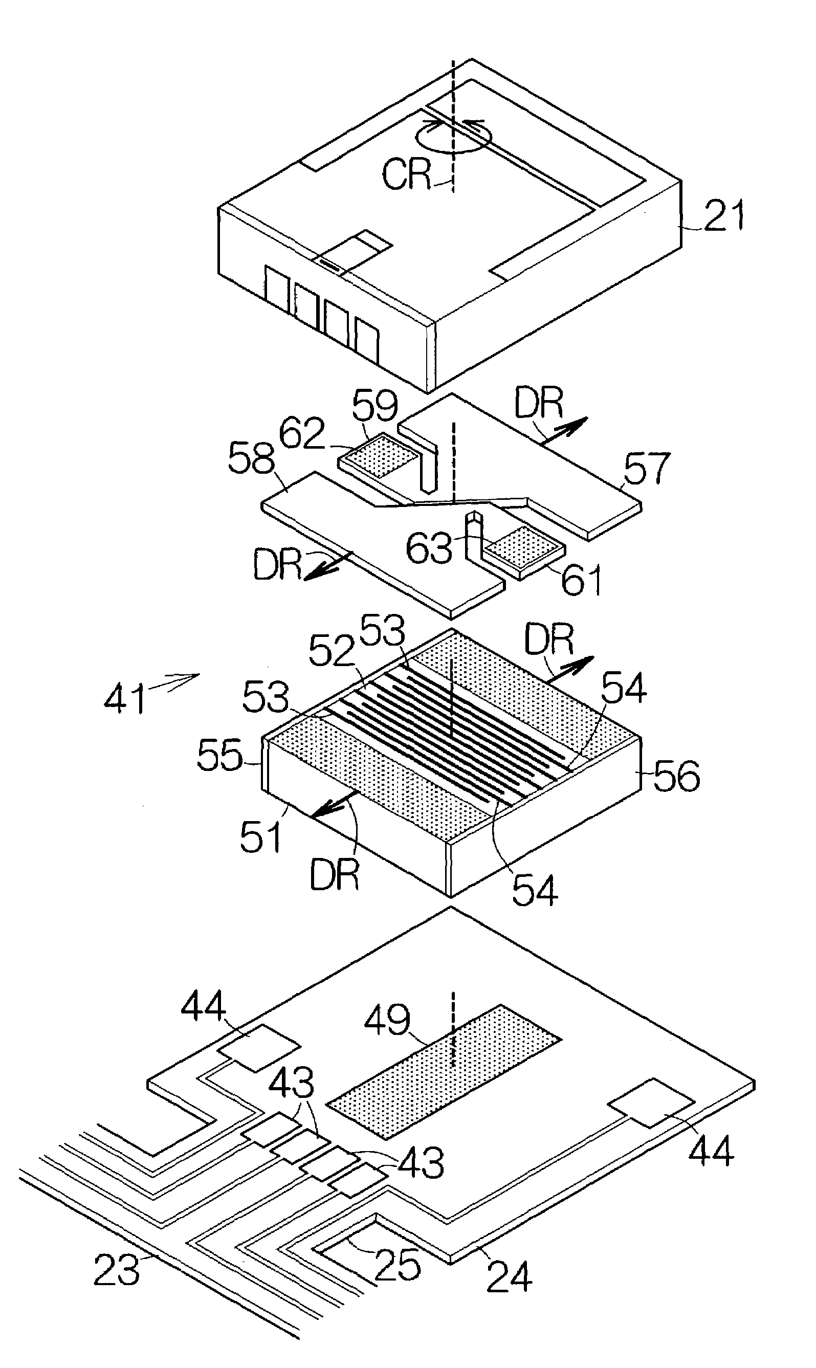
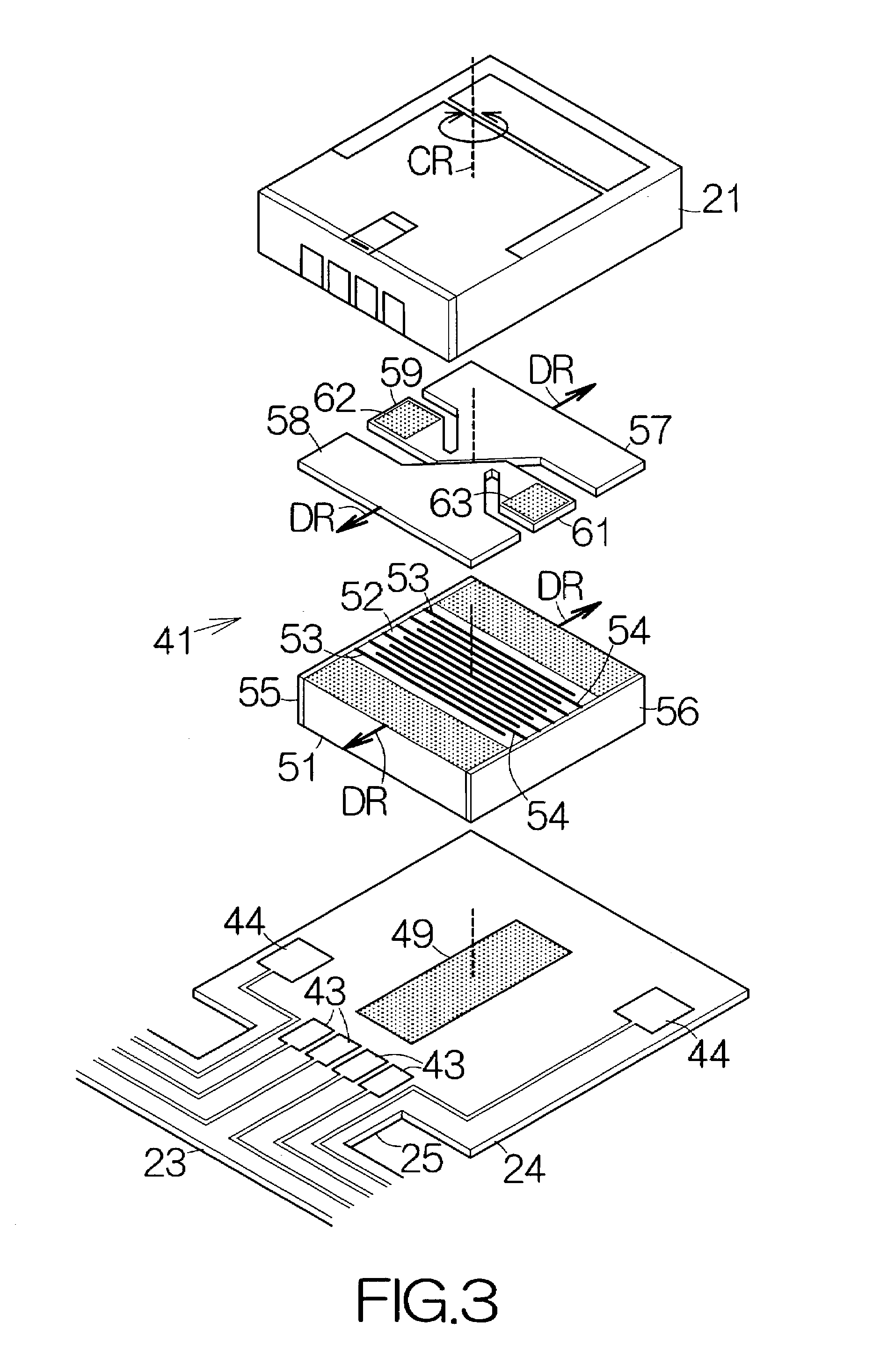
[0055]As shown in FIG. 3, the microactuator 41 of a first embodiment includes a piezoelectric element 51 fixed to the plate member 24 with a first adhesive layer 49. The first adhesive layer 49 is allowed to extend outward from the rotational axis CR toward the periphery. The first adhesive layer 49 has a constant thickness ranging from 5 μm to 20 μm, for example. The first adhesive layer 49 may be made of an epoxy adhesive or the like.
[0056]The piezoelectric element 51 is made of a multilayered structure 52 of piezoelectric ceramic thin plates. The piezoelectric ceramic thin plates are sequentially layered from the inflow or front side to the outflow or rear side in the attitude upright to the surface of the plate member 24. First and second electrode layers 53, 54 are alternately interposed between the adjacent piezoelectric ceramic thin plates. The piezoelectric ceramic thin plates may be made of a piezoelectric material such as PNN-PT-PZ, for example.
[0057]A first electrode term...
second embodiment
[0074]FIG. 10 schematically illustrates the structure of the microactuator 41a according to the present invention. The microactuator 41a includes a pair of piezoelectric elements 71, 71 extending in parallel to each other from the inflow end to the outflow end in the longitudinal direction of the flying head slider 21. The inflow ends of the individual piezoelectric elements 71 are coupled to the plate member 24 of the flexure 23 at first places 72a. First adhesive layers 72 serve to establish the connections at the first places 72a. Likewise, the outflow ends, opposite to the inflow ends, of the individual piezoelectric elements 71 are coupled to the plate member 24 of the flexure 23 at second places 72b. First adhesive layers 72 serve to establish the connections at the second places 72b. The first adhesive layers 72 are located symmetrically around the rotational axis CR within a plane perpendicular to the rotational axis CR. The first adhesive layers 72 are individually coupled ...
third embodiment
[0081]FIG. 11 schematically illustrates the structure of a microactuator 41b according to the present invention. The microactuator 41b includes first and second piezoelectric elements 82a, 82b extending in parallel with each other in the longitudinal direction of the flying head slider 21. The inflow end of the first piezoelectric element 82a is coupled to the plate member 24 of the flexure 23. Likewise, the outflow end of the second piezoelectric element 82b is coupled to the plate member 24 of the flexure 23. Electrically-conductive first adhesive layers 83 serve to establish the connections. The first adhesive layers 83 are located symmetrically around the rotational axis CR within a plane perpendicular to the rotational axis CR. The first adhesive layers 83 are individually coupled to the electrically-conductive pattern 44.
[0082]The individual piezoelectric element 82a, 82b is made of a multilayered structure of piezoelectric ceramic thin plates. The piezoelectric ceramic thin p...
PUM
| Property | Measurement | Unit |
|---|---|---|
| thickness | aaaaa | aaaaa |
| thickness | aaaaa | aaaaa |
| thickness | aaaaa | aaaaa |
Abstract
Description
Claims
Application Information