
Graphics engine for high precision lithography

a high-precision lithography, graphing engine technology, applied in the direction of digitally marking record carriers, photomechanical devices, instruments, etc., can solve the problems of increasing complexity and density of chips, and the pattern of these circuits becoming even more complex than the circuits, so as to facilitate compensation

Inactive Publication Date: 2007-11-27
MICRONIC LASER SYST AB
View PDF33 Cites 54 Cited by
  • Summary
  • Abstract
  • Description
  • Claims
  • Application Information

AI Technical Summary

Benefits of technology

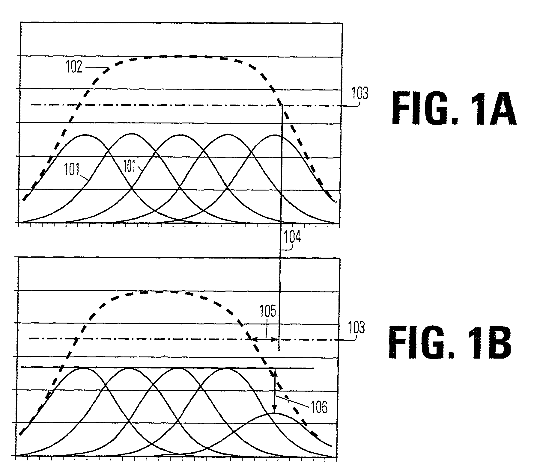
[0006]Aspects of the present invention may be combined to process large volumes of geometric figures and generate precise patterns on work pieces using SLM projection technology, for instance. Additional aspects of the present invention facilitate compensation for variations in resist response and other process variable.
[0009]An additional embodiment of the present invention is use of the guard zone as an alternative to clipping. This includes providing a smaller address window corresponding to a memory; providing a larger address window creating a guard zone around the smaller addressing window, which is addressable but does not correspond to the memory; receiving a polygon contained within the larger addressing window; rendering at least sections of the polygon into the larger address window; and writing data for the rendered sections of the polygon within the smaller address window to the memory while discarding rendered sections of the polygon outside the smaller window. A further aspect of this embodiment is that the rendering step may be carried out without distinction between portions of the polygon that are inside, versus outside the smaller addressing window. This method may be carried out without clipping the polygon to fit the smaller addressing window. The discarding of rendered sections of the polygon may take place before data is sent to a memory controller, by a filter, or in the memory controller, by comparing memory address signals with valid addresses of the smaller addressing window in using the result of the comparison to control one or more memory arbitration signals, such as write enable signals. This embodiment and its various aspects may be further enhanced by including a stamp of filtering a set of polygons so that at least a portion of the polygon received and rendered lies inside the smaller addressing window.

Problems solved by technology

Over time, chips have become increasingly complex and dense, as processors, memory circuits and other semi-conductors have gained greater capacity.
Patterns for these circuits have become even more complex than the circuits, as optical proximity and laser proximity correction features have been added to the patterns.
Another challenge for manufacturers is to compensate for variations in process chemistries, such as variations in responsiveness of resists to exposing radiations.

Method used


Image

  • Graphics engine for high precision lithography
  • Graphics engine for high precision lithography
  • Graphics engine for high precision lithography

Examples


first embodiment

Sliding Displacement Algorithm—First Embodiment

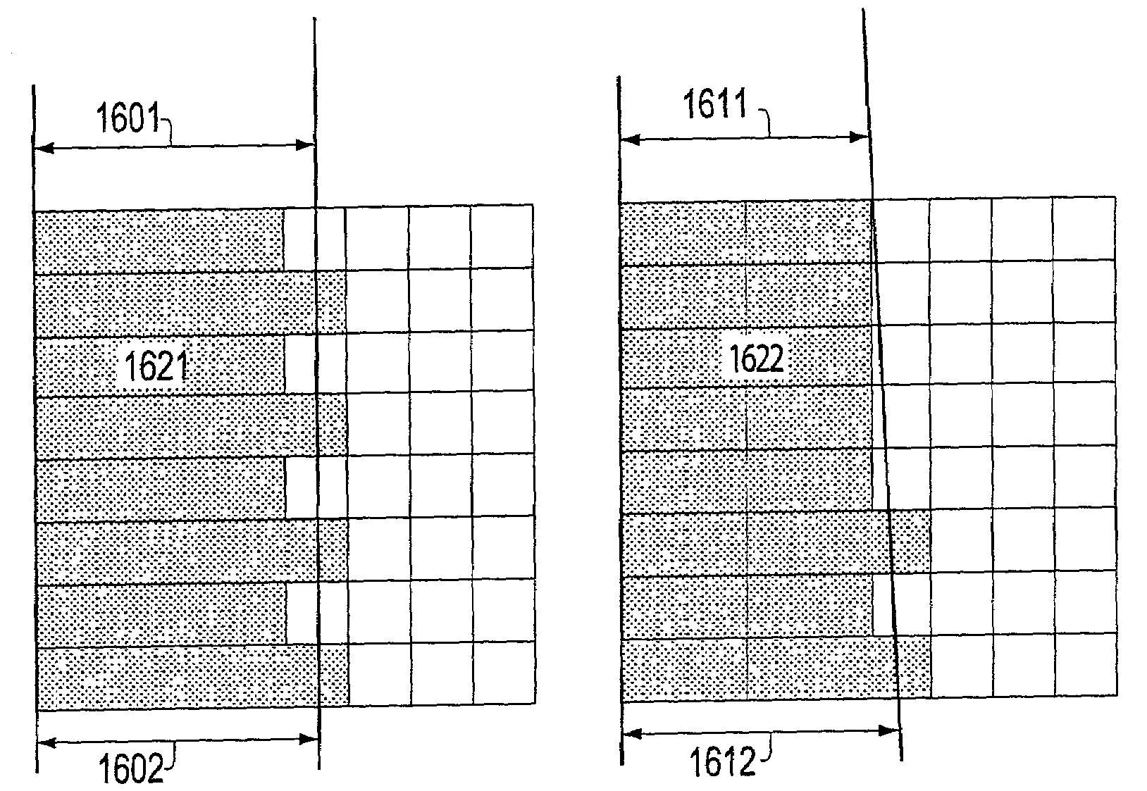
[0174]The sliding displacement algorithm is illustrated by FIGS. 19A-B. For displacement along an axis that is nearly parallel to the edge being displaced, the following function can be used:

[0175]p′⁡[i]=d⁢⁢XmaxVal⁢p⁡[i+sgn⁢(cdX)⁢sgn⁢(fX)]+(maxVal-dX)maxVal⁢p⁡[i].

Where, maxVal=maximum brightness value of a filled pixel (64 in this example). This algorithm depends only on the gray value of one adjacent pixel, either to the left or right depending on the signs of the parameters cdX and fX. The formula essentially calculates the weighted mean between two pixels, where the weighting factors add up to one. Different weighting factors can be applied to compensate for errors observed when the method is applied. The displacement illustrated in this figure is a dilation of 32 / 64. The resulting weights are half the brightness of the current pixel plus half the brightness of its right-hand neighbor. The edge 1911 is displaced to the left 1912. Pix...

second embodiment

Sliding Displacement Algorithm—Second Embodiment

[0176]An alternative formula for sliding displacement is:

[0177]p′⁡[i]=max⁢{0min⁢{64(1-dX64)⁢p⁡[i]+dX64*p⁡[i+sgn⁡(c⁢⁢d⁢⁢X)⁢sgn⁡(fx)]

where p[i] is the center pixel. If more than 64 sub-pixels represent a single pixel, the alternative min value is adjusted accordingly.

Displacement by Sliding and Filling Up

[0178]Variations in application of sliding and filling up edge displacements are illustrated in FIGS. 48-49. The approach used may depend on the angle of the edge detected by the gradient filters. In each variation, first the slide operation is performed on every central pixel of the neighborhood along either the x- or y-axis. Then a fill-up operation is made on the center pixel of the neighborhood in the opposite direction. A weight factor of 1 is used, but can be modified to proportionally increase or reduce the response of the algorithm to a displacement parameter.

[0179]A variation on the fill up and sliding algorithms described above...

examples

[0368]

Set arraySet validCommentSet 0—FalseNo modification on set 0Set 1—FalseNo modification on set 1Set 2WWWGTruevSet 3—FalsevSet 0—FalseNo modification on set 0Set 1WWGGTrueSet 1 is modified with symbols WWGGSet 2WWWGTrueSet 2 is modified with symbols WWWGSet 3—FalseV

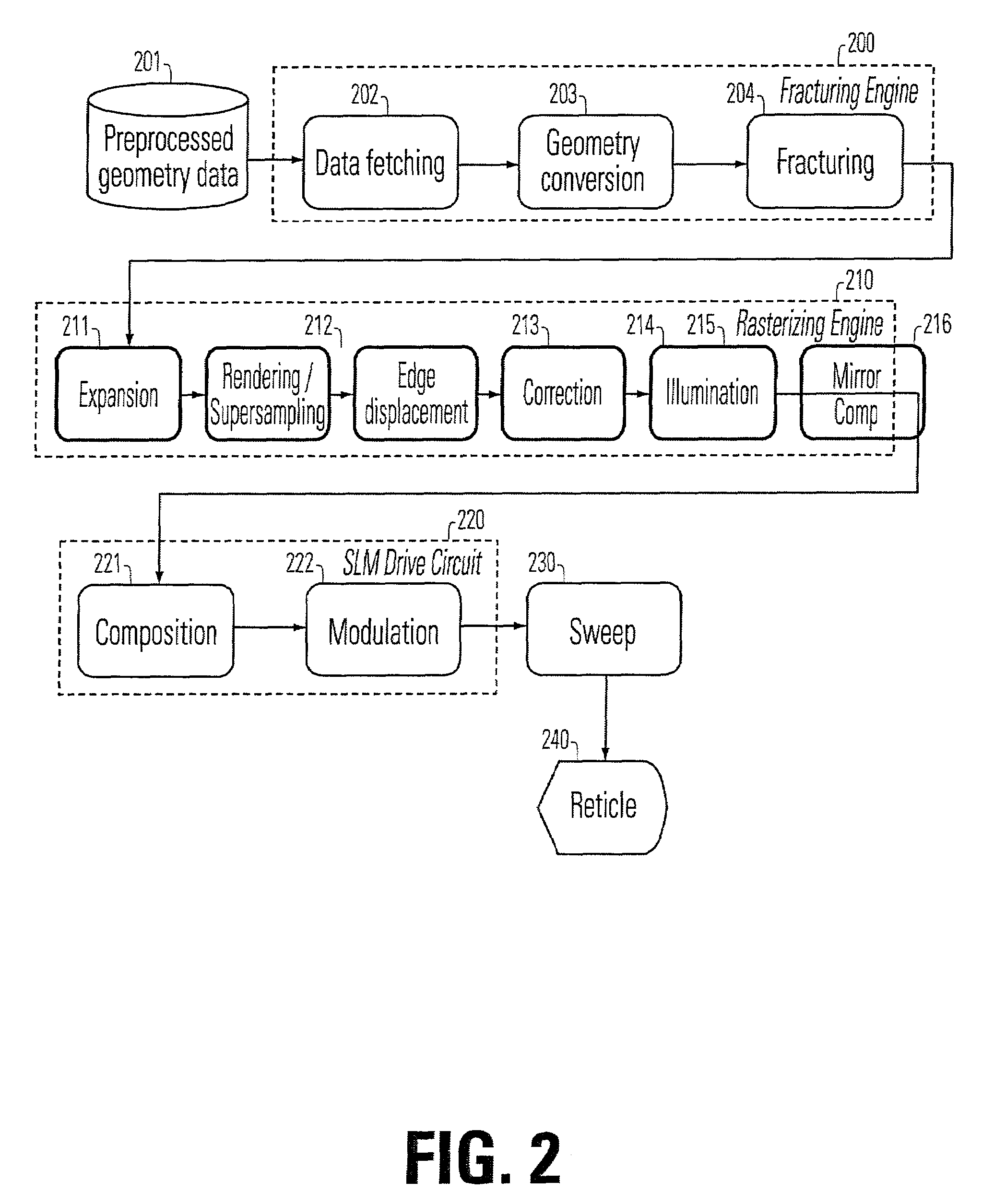
[0369]The PMFB agent 4231 shares signals with the ZBT-controller 3804A, PMFB-AccSeqGen 4231 and the Access Qualifier FIFO 4232. The interface between PMFB AccSeqGen and PMFB-Agent is mentioned above. The interface between AccQua FiFo 4232 and PMFB-Agent 4231 includes sending Access Qualifiers to the FiFo. To allow new data to be written, a Write Enable is needed as well as a FiFo status flag, e.g., fifo_full or fifo_overrun. The Interface between PMFB-Agent 4231 and the ZBT-controller 3804A includes: Address, data in, data out, read_write, and byte enable signals. In addition, the Rendering Window Logical Operator (RWLOper), included in the generic container, is needed to determine which logical operator to use to per...


PUM

PropertyMeasurementUnit
anglesaaaaaaaaaa
anglesaaaaaaaaaa
angleaaaaaaaaaa

Abstract

The present invention includes a method to use a phase modulating micromirror array to create an intensity image that has high image fidelity, good stability through focus and good x-y symmetry. Particular aspects of the present invention are described in the claims, specification and drawings.

Description

RELATED APPLICATION INFORMATION[0001]This application is related to Provisional Application No. unassigned, filed the same day as this application in the United State Patent and Trademark Office, entitled IMPROVED METHOD AND APPARATUS USING AN SLM, by inventors Torbjorn Sandstrom and Jarek Luberek, which simultaneously filed application is incorporated herein by reference, as if set forth in its entirety.FIELD OF THE INVENTION[0002]The invention relates to rendering high precision images with sub-pixel resolution. This invention is applicable to production of reticles and large area masks, direct writing of patterns and inspection of reticles or other patterned work pieces. Aspects of the invention can apply to both SLM and scanning technologies.BACKGROUND OF THE INVENTION[0003]Equipment for semi-conductor manufacturing includes writers and inspection equipment for producing images on reticles and large area masks, for direct writing of patterns for chips, and for inspection of patt...

Claims


Application Information

Patent Timeline
Patent Type & Authority Patents(United States)
IPC IPC(8): G06K9/40G06K9/36G06K9/46G02B26/08G03F1/00G03F1/76G03F7/20G06T15/00H01L21/027
CPCG03F1/14G03F1/76G06T15/00G03F7/70508G03F7/70291G06T1/00
Inventor OLSSON, MARTINGUSTAVSON, STEFANSANDSTROM, TORBJORNELMFORS, PER
Owner MICRONIC LASER SYST AB
Learn More