
Method of manufacturing armature of rotary electric machine

a technology of rotary electric machines and armatures, which is applied in the direction of magnetic circuit rotating parts, magnetic circuit shapes/forms/construction, magnetic bodies, etc., can solve the problems of difficult to further enhance the manufacturing speed, difficult to insert conductors, and certain limits in the enhancement of manufacturing speed in an automated assembly line. achieve the effect of speeding up the manufacturing process, light weight and small siz

Active Publication Date: 2007-12-04
DENSO CORP
View PDF20 Cites 18 Cited by
  • Summary
  • Abstract
  • Description
  • Claims
  • Application Information

AI Technical Summary

Benefits of technology

The present invention provides an improved method of manufacturing an armature of a rotary electric machine and an armature manufactured by the improved method. The method speeds up the process of manufacturing the small-sized and light-weight armature. The armature is composed of an armature core made by laminating plural steel plates, an armature winding disposed in slots formed in the armature core, and an armature shaft connected to the armature core. The armature winding is composed of plural conductors electrically connected one another. The method involves forming a conductor bar including plural conductors connected in a straight line, inserting the conductors into slots of the armature core, bending and skewing the conductors, and electrically and mechanically connecting the ends of the conductors to form the armature winding. The armature core has a simplified assembly process, and the outer surface of the side portions is used as a commutator surface, which reduces the axial length of the armature.

Problems solved by technology

The conductor has to be formed one by one using a complex transfer press, and therefore it has been difficult to further enhance the manufacturing speed.
Further, it has not been easy to insert conductors, each having a U-shape and skewed ends, into the slots of the armature core.
Therefore, there has been a certain limit in enhancing manufacturing speed in an automated assembling line.

Method used


Image

  • Method of manufacturing armature of rotary electric machine
  • Method of manufacturing armature of rotary electric machine
  • Method of manufacturing armature of rotary electric machine

Examples


Embodiment Construction

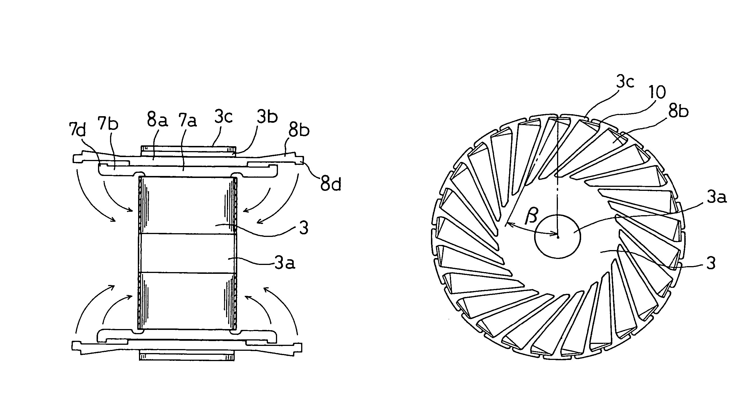
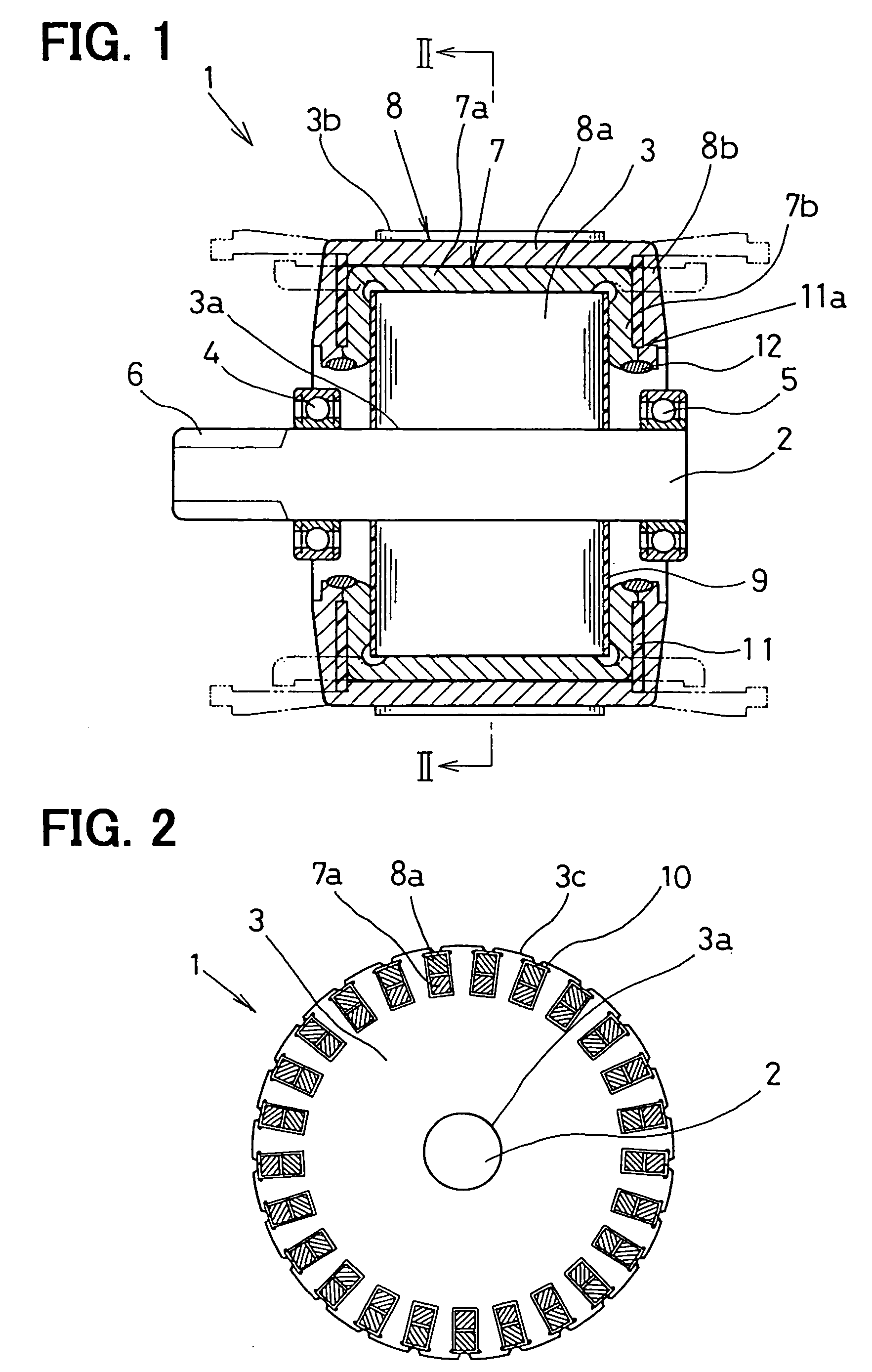
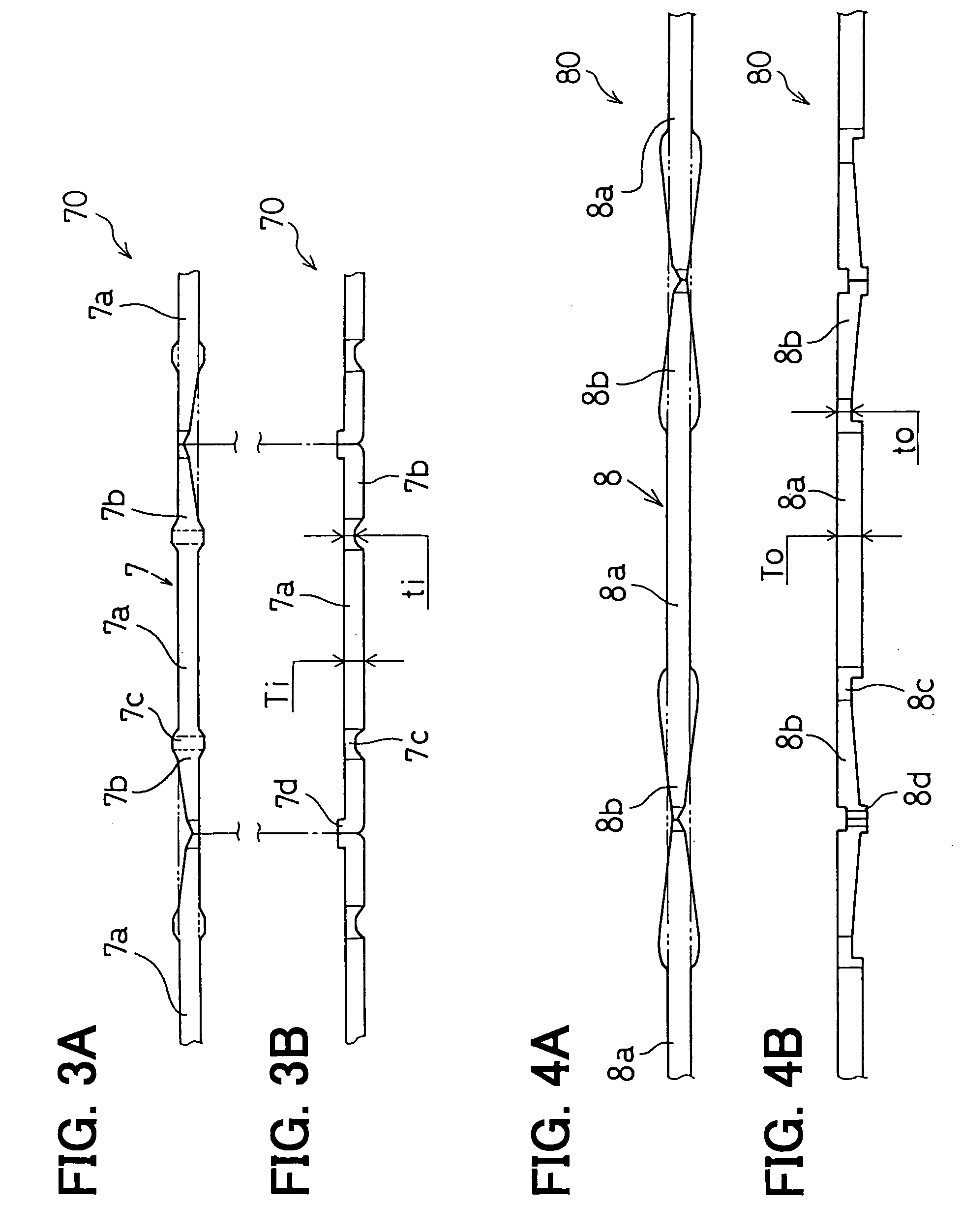
[0024]A preferred embodiment of the present invention will be described with reference to accompanying drawings. In this embodiment, the present invention is applied to an armature of a starter motor for cranking an internal combustion engine. As shown in FIG. 1, the armature 1 is composed of an armature core 3, an armature shaft 2 fixedly connected to the center of the armature core 3, and conductors 7, 8 inserted into slots 3b of the armature core 3. Dotted lines show positions of the conductors 7, 8 before their side portions are bent.

[0025]The armature shaft 2 is rotatably supported by a pair of bearings 4, 5 that is fixedly held in a motor housing (not shown). At an left end (in FIG. 1) of the armature shaft 2, a sun gear 6, which constitutes a part of a planetary gear speed reduction mechanism, is provided. That is, rotational torque of the armature 1 is transferred to a pinion gear of an engine through the planetary gear speed reduction mechanism. The armature core 3 is forme...


PUM

PropertyMeasurementUnit
thicknessaaaaaaaaaa
angleaaaaaaaaaa
widthaaaaaaaaaa

Abstract

An armature of a rotary electric machine composed of an armature core, an armature winding and a shaft is manufactured in the following manner. A conductor bar including plural conductors connected in line is formed, and each conductor is cut out from the conductor bar. The conductor in a straight shape is inserted into each slot of the armature core, and then both side portions of the conductor are bent at substantially right angle so that the side portions are positioned along axial end surfaces of the armature core. The side portions are further skewed and electrically connected to form the armature winding. An outer surface of the side portions circularly arranged on the axial end surface of the armature core is used as a commutator surface.

Description

CROSS-REFERENCE TO RELATED APPLICATION[0001]This application is based upon and claims benefit of priority of Japanese Patent Application No. 2003-305891 filed on Aug. 29, 2003, the content of which is incorporated herein by reference.BACKGROUND OF THE INVENTION[0002]1. Field of the Invention[0003]The present invention relates to a method of manufacturing an armature of a rotary electric machine such as a direct current motor and to the armature manufactured by that method.[0004]2. Description of Related Art[0005]Recently, it has been becoming more important to develop automotive parts that are light in weight and small in size to reduce fuel consumption in an automobile vehicle and thereby to cope with the problem of global warming. One example of a light and small motor, which was invented by one of inventors of the present invention, is disclosed in JP-B2-2924605. In the armature of this motor, a conventional commutator is eliminated, and a commutator formed by part of the conduct...

Claims


Application Information

Patent Timeline
Patent Type & Authority Patents(United States)
IPC IPC(8): H02K15/04H02K15/09H02K3/04H02K3/12H02K3/34H02K3/51H02K13/04H02K15/00H02K15/02H02K23/00
CPCH02K3/12H02K15/0056H02K15/0081Y10T29/49012Y10T29/49009Y10T29/49073H02K1/165
Inventor NIIMI, MASAMISHIGA, TSUTOMUOOMI, MASANORI
Owner DENSO CORP
Learn More