Hydraulic brake booster

a brake booster and hydraulic technology, applied in the field of automobile technology, can solve the problems of special complicated travel limiter assembly, need for arresting the extra travel, and withdrawal of possible steering loss during brake application

Inactive Publication Date: 2007-12-04
BRAKES INDIA LTD
View PDF6 Cites 0 Cited by
  • Summary
  • Abstract
  • Description
  • Claims
  • Application Information

AI Technical Summary

Benefits of technology

[0006]Another objective of the present invention is to have a simple configuration of operation that avoids the steering loss during certain operating modes.
[0025]United States Patent No. US2005121973 discloses a hydraulic booster which applies output hydraulic pressure of a hydraulic power source to a boosted hydraulic pressure chamber after regulating the output hydraulic pressure as a control piston operates to balance reaction force generated by hydraulic pressure of the boosted hydraulic pressure chamber with brake operating input; and a brake stroke simulator installed between the brake operating member and the control piston in order for a driver to feel operating strokes of the brake operating member. The brake stroke simulator has: an input member axially slidably housed in the control piston of a cylindrical shape and linked to the brake operating member; and an elastic body interposed between the input member and the control piston. The elastic body is formed into a tubular shape so as to come into resilient contact with an inner circumference of the control piston by expanding its diameter under the action of axial compressive force generated by forward movement of the input member. Consequently, the brake stroke simulator allows large hysteresis width in relationship between brake operating stroke and operating load.

Problems solved by technology

This has the drawback of possible steering loss during brake applications.
Secondly, in some of the currently available hydraulic boosters, because of the high ratio of input to output travel, there is a need for arresting the extra travel during manual operations.
This requires a special complicated travel limiter assembly.
Thirdly, in the currently available hydraulic boosters, the input rod and the trigger mechanism are in two different axes, requiring complicated trigger mechanisms.
The performance of these boosters is therefore ramp rate sensitive.
This has the drawback of brake not being effective at high ramp rates.
Fifthly, in the currently available hydraulic boosters, the accumulator comes into force only during fail-safe mode.
The trigger mechanism for the fail-safe mode is quite complicated and involves very intricate machining.
On failure of the booster and displacement of the booster piston exclusively by way of the brake pedal, the booster sleeve will remain in its initial position which brings about an abrupt change in ratio.

Method used


Image

  • Hydraulic brake booster
  • Hydraulic brake booster
  • Hydraulic brake booster

Examples


Embodiment Construction

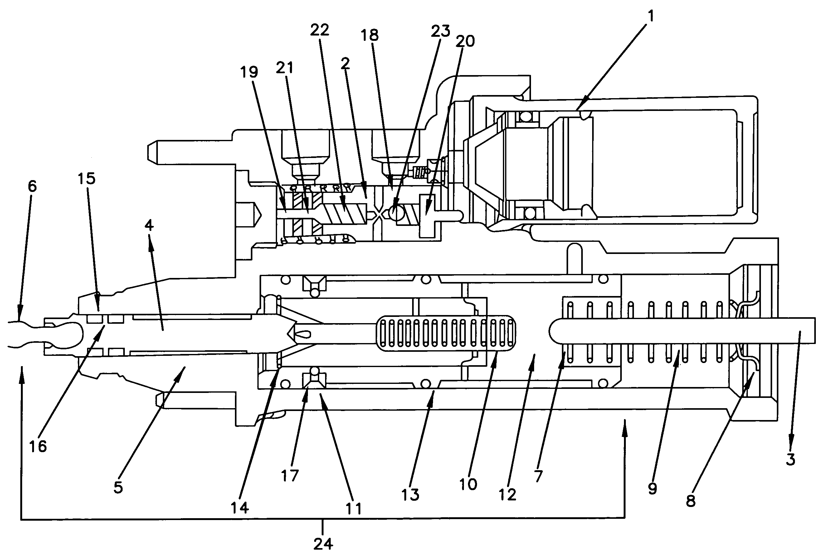
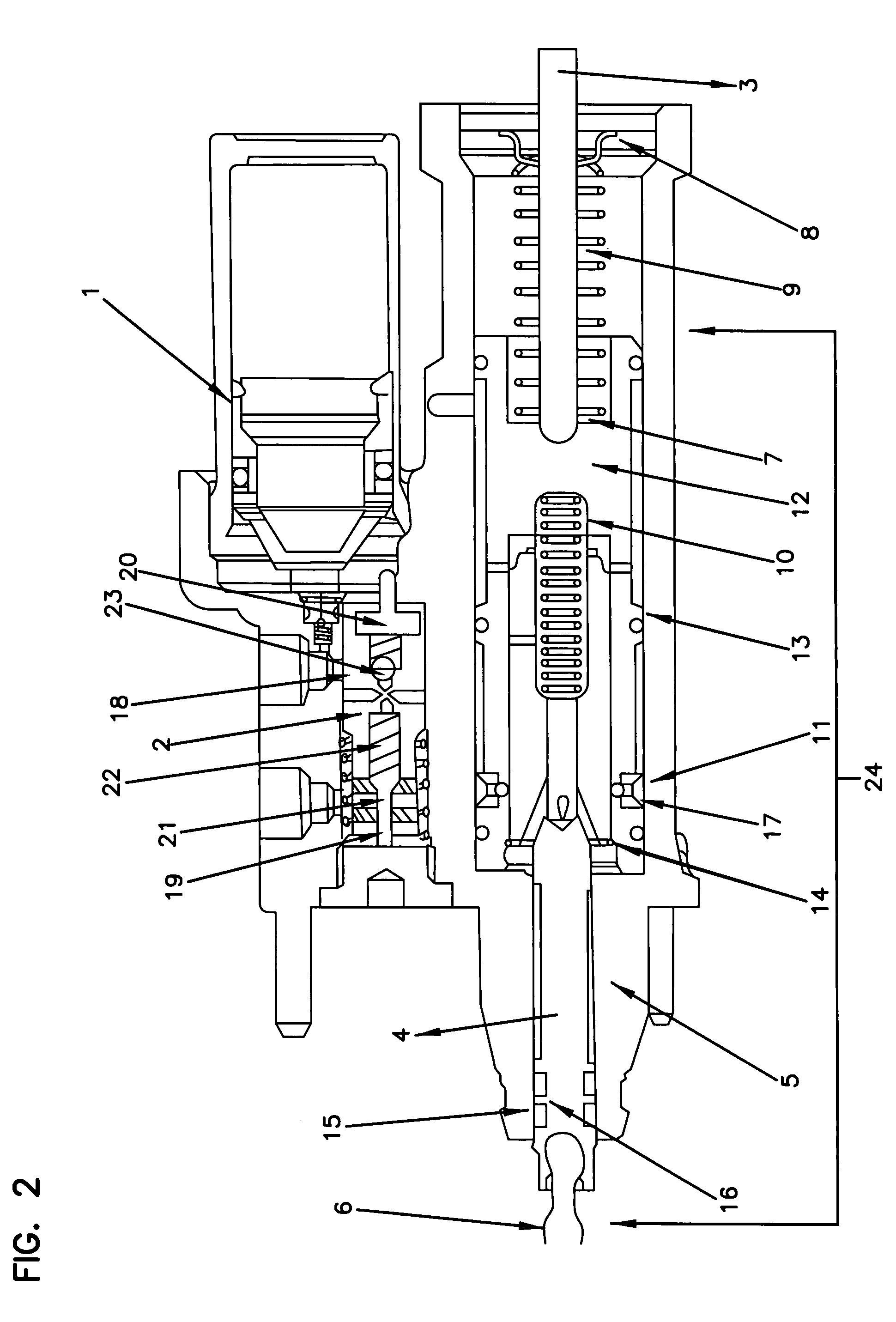
[0040]A hydraulic brake booster system according to an embodiment of the present invention will now be described hereinafter with reference to FIGS. 1 to 10.

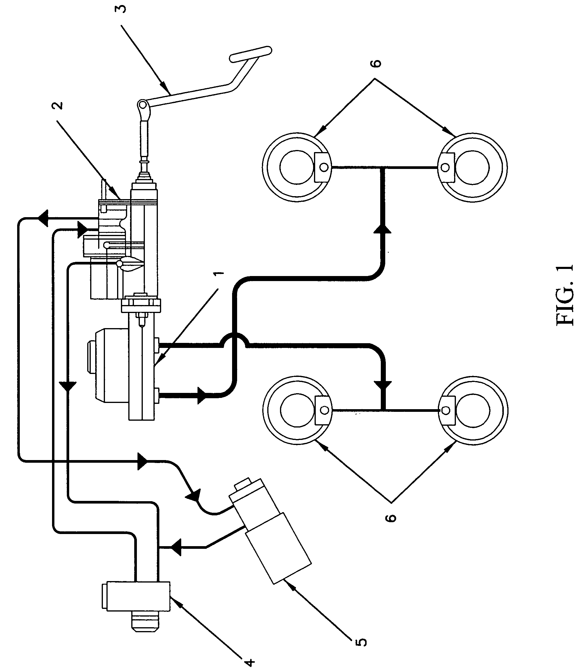
[0041]The first exemplary embodiment of the brake system shown in FIG. 1 has a master cylinder 1, a hydraulic brake booster 2, a brake pedal 3, a pump & reservoir 4, a steering gear 5, and front and rear brakes 6, which are of a design known in the prior art. A hydraulic brake booster 2 for motor vehicles has a brake cylinder 1 that can be actuated especially by a brake pedal 3, a reservoir of brake fluid 4, a braking means that are coupled to at least one vehicle wheel 6 and can be linked to the brake cylinder 1, a hydraulic pump 4 that supplies pressurized fluid to an accumulator to provide brake fluid under pressure in a controlled manner to the braking means through a control valve arrangement.

[0042]As shown in FIG. 1, an input portion of a brake booster 2 is connected a master cylinder 1 by the output rod driven by a brake ...


PUM


Abstract

An hydraulic brake booster for an automobile hydraulic system comprising of a boost cylinder, a boost piston and a boost chamber defined by a boost piston working in a bore in a body and being adapted to apply an output force to an output rod in response to a pressure applied to a boost chamber under a control valve, in turn responsive to an input force from input rod, wherein the input rod move in a forward operating direction up to a prescribed point so as to prevent fluid from a radial high pressure supply port from entering the boost chamber when the booster is in an inoperative position, any added movement of the input rod in a forward operating direction lifts the boost piston ball and uncovers the supply port so as to allow pressurized fluid into the boost chamber from the accumulator.

Description

FIELD OF INVENTION [0001]The present invention belongs to the field of automobile technology and relates to a mechanical invention consisting of a hydraulic booster brake system that utilizes pre-stored high hydraulic pressure generated from a hydraulic pump to produce output force corresponding to a desired brake application. More particularly the invention relates to a hydraulic booster in which an input rod moved by an input force applied to the pedal rod by an operator to regulate the flow of pressurized fluid from a source to a boost chamber. The regulated pressurized fluid acts on the boost piston to provide an operational force that moves pistons in the master cylinder to pressurize fluid that is supplied to wheel brakes, which in turn moves the brake shoes to effect a brake application.BACKGROUND OF INVENTION [0002]A conventional hydraulic brake booster operates in three different modes namely rest mode, apply mode and hold mode. In conventional booster assembly during rest ...

Claims


Application Information

Patent Timeline
Patent Type & Authority Patents(United States)
IPC IPC(8): B60T13/14B60T13/10
CPCB60T13/145
Inventor VISWANATHAN, MALAIAPPANDHARMAR, TRAO, R SRINIVASA
Owner BRAKES INDIA LTD
Why Eureka
Try Eureka