Device, system, and method for structural health monitoring

a technology for structural health and monitoring, applied in the direction of force/torque/work measurement apparatus, mechanical vibration separation, tension measurement, etc., can solve the problems of limiting the placement of sensors with large connectors and wiring to the interior of aircraft, affecting the safety of personnel, and requiring non-destructive inspection of aircraft structures

Inactive Publication Date: 2007-12-04
THE BOEING CO
View PDF3 Cites 44 Cited by
  • Summary
  • Abstract
  • Description
  • Claims
  • Application Information

AI Technical Summary

Benefits of technology

[0013]The interface module is coupled to a phased array sensor assembly that can be permanently adhered to a structure to be inspected. An alignment check is performed to ensure that a connector head on the interface module is properly aligned with the sensor assembly such that each of the contact pads that are exposed on the sensor assembly is in electrical contact with corresponding contacts in the connector head. The interface module is then coupled to a data acquisition computing device that generates an electrical signal using a function generator. The electrical signal is sent to the sensor assembly via the interface module to cause each piezo-electric disk in the sensor assembly to transduce the electrical signal and induce ultrasonic strain waves into the structure being inspected. Ultrasonic strain waves present in the structure being inspected are received in each piezo-electric element and converted to electrical signals that are sent to the data acquisition computer for analysis. The data acquisition computer software can construct an image of anomalies in the area serviced by the sensor assembly on the structure being inspected.

Problems solved by technology

Damage tolerant structures such as aircraft frequently require non-destructive inspection.
This currently limits placement of sensors with large connectors and wiring to the interior of aircraft to avoid excessive aerodynamic drag.
But, interior installations may be restricted by the bulk of sensors from prior solutions.
Retrofit installation requirements and structural access limitations may require, however, that sensing systems and electrical connectors for sensors be located on the exterior of aircraft surfaces, in the airstream, or in interior locations having limited space available.
Additionally, tight clearances exist on interior structures that may also require thin sensing elements.

Method used


Image

  • Device, system, and method for structural health monitoring
  • Device, system, and method for structural health monitoring
  • Device, system, and method for structural health monitoring

Examples


Embodiment Construction

[0022]The following detailed description of embodiments refers to the accompanying drawings, which illustrate specific embodiments of the invention. Other embodiments having different structures and operations do not depart from the scope of the present invention.

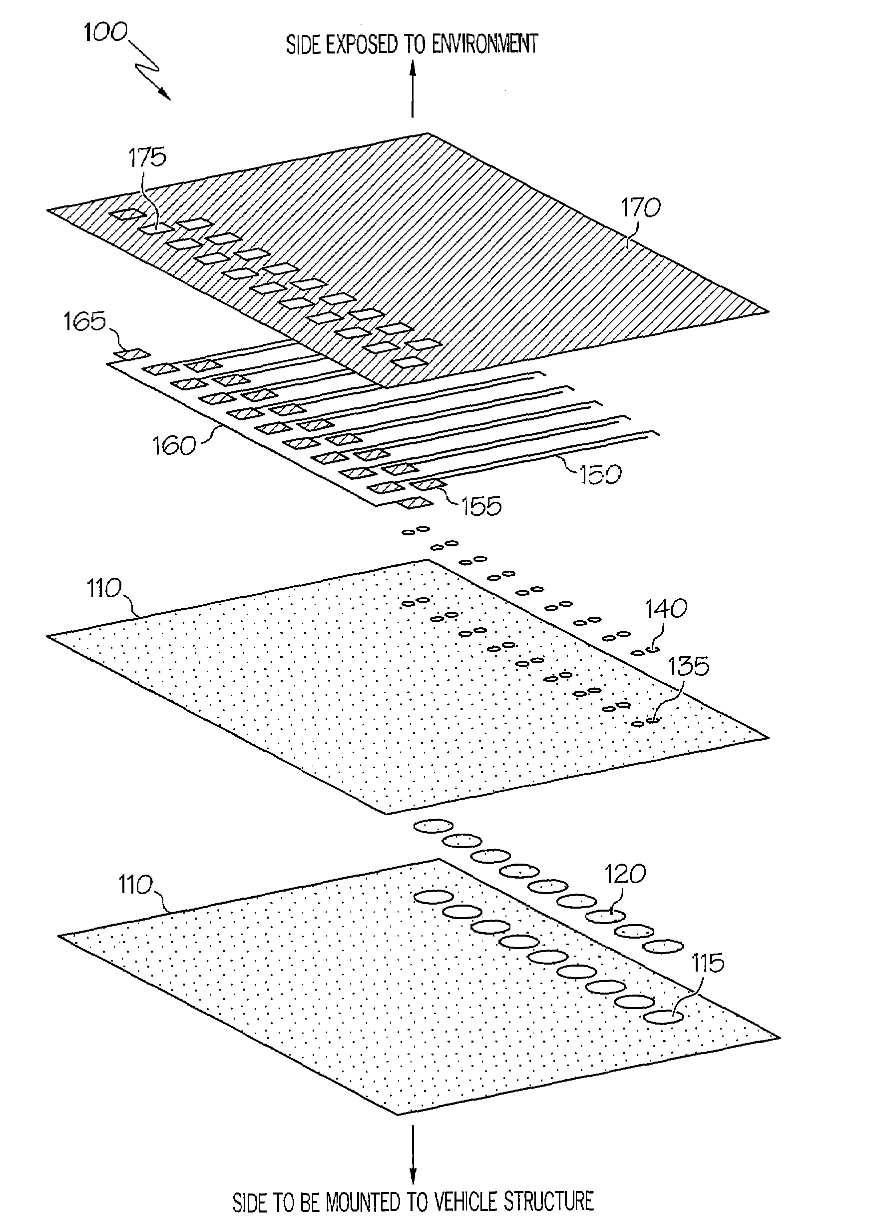
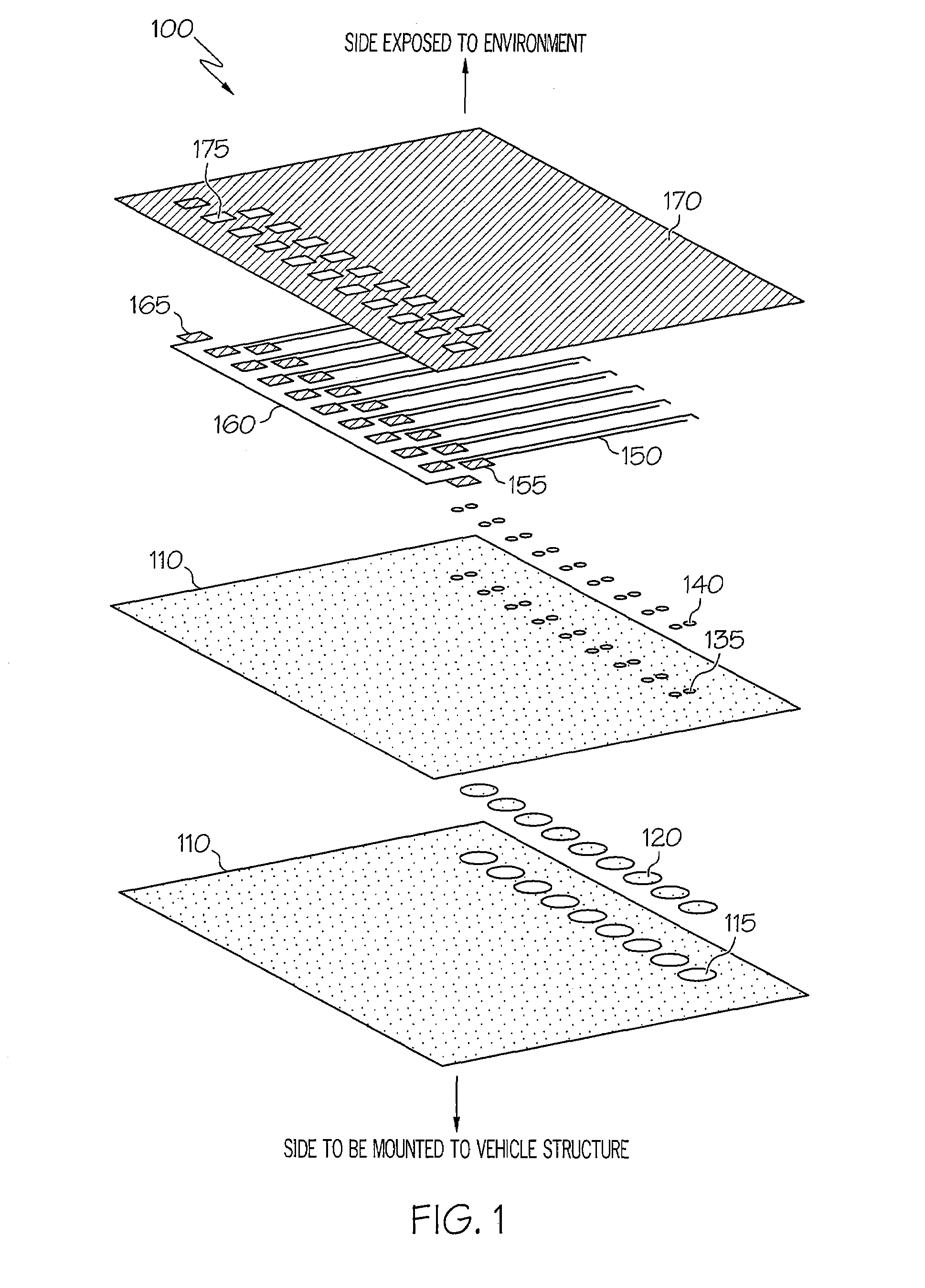
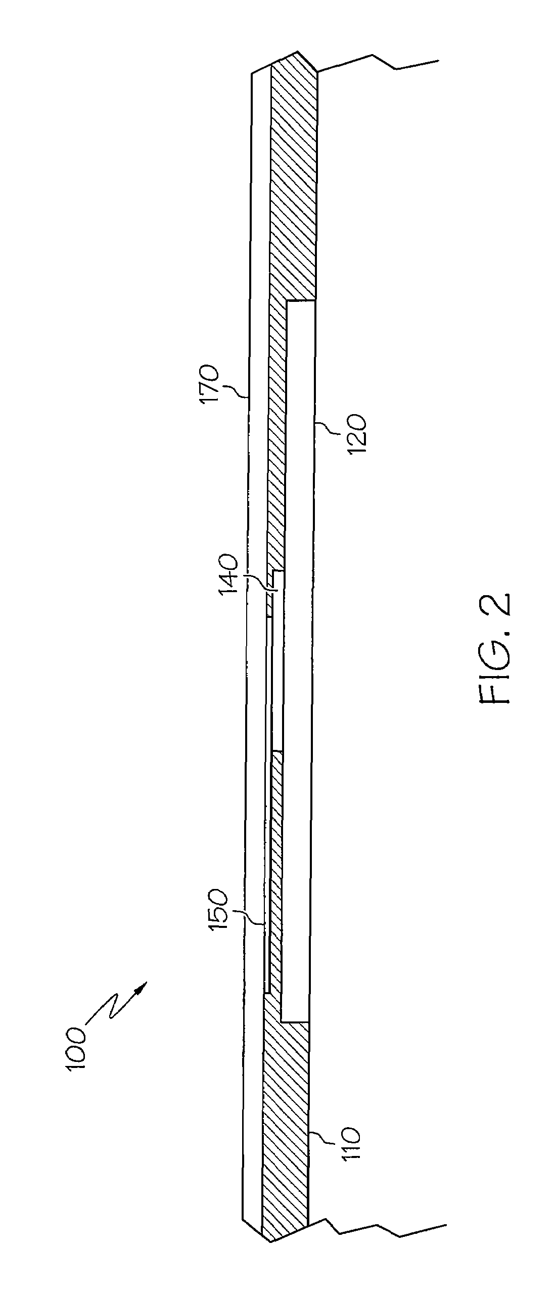
[0023]The present invention describes a thin (low-profile) phased array sensor and sensing system and method intended for structural health monitoring of a large structural area using piezoelectric elements to generate and receive ultrasonic waves. It can be permanently attached to the structure under inspection. The sensor includes electrical contact pads to replace bulky connectors or permanently attached wiring. The thin, flexible, conformal design and the method of electrical access allow for installation of the sensor on the exterior surface of an aircraft, for example, or on interior structures with close clearances.

[0024]FIG. 1 is an illustration of an example of a thin profile flexible sensor assembly 100 in an expl...


PUM


Abstract

A phased array sensor assembly is presented that can be permanently adhered to and impart ultrasonic waves to a structural surface and receive ultrasonic waves from a structural surface. The sensor assembly includes piezo-electric disks, a plurality of electrically conductive epoxy film adhesive contacts positioned such that an electrical coupling is formed with the piezo-electric disks, piezo transducer flex wire trace circuits aligned to be electrically coupled respectively with the electrically conductive epoxy film adhesive contacts on one end and including a plurality of wire trace electrical contact pads on the other end, and a flexible polyimide layer. The polyimide layer includes laser ablated areas for exposing the contact pads such that they can be electrically coupled with an external device.

Description

FIELD OF THE INVENTION[0001]The present invention relates to the ability to monitor the structural integrity of a structure or a specific vehicle, such as an aerospace vehicle, watercraft, terrestrial vehicle or the like.BACKGROUND OF THE INVENTION[0002]Damage tolerant structures such as aircraft frequently require non-destructive inspection. In-situ (permanently mounted to the vehicle structure) sensor systems that can cover large areas of a structure may require multiple sensing elements to achieve a satisfactory resolution, each with its own discrete wiring that is heavy and complex. This currently limits placement of sensors with large connectors and wiring to the interior of aircraft to avoid excessive aerodynamic drag. But, interior installations may be restricted by the bulk of sensors from prior solutions.[0003]Retrofit installation requirements and structural access limitations may require, however, that sensing systems and electrical connectors for sensors be located on th...

Claims


Application Information

Patent Timeline
Patent Type & Authority Patents(United States)
IPC IPC(8): G01D7/00
CPCB06B1/0622B06B1/0696
Inventor MALKIN, MATTHEW C.KEARNS, JUSTIN D.
Owner THE BOEING CO
Why Eureka
Try Eureka