Pump drive motor control apparatus

a technology of motor control and push rod, which is applied in the direction of machines/engines, braking systems, and positive displacement liquid engines, etc., can solve the problems of easy failure of abs control, failure of antilock brake system to achieve brake fluid pressure control, and the hydraulic circuit of the hydraulic brake system of the antilock brake system

Active Publication Date: 2007-12-04
ADVICS CO LTD
View PDF11 Cites 2 Cited by
  • Summary
  • Abstract
  • Description
  • Claims
  • Application Information

AI Technical Summary

Benefits of technology

[0011]Accordingly, an object of the present invention is to provide a pump drive motor control apparatus for controlling the rotational speed of a motor for driving a pump, which apparatus can detect in a simple and reliable manner a drop in discharge flow rate of the pump stemming from a load imposed on the pump, and increase the discharge flow rate.
[0016]The present invention has been accomplished while attention has been paid to such a phenomenon. Specifically, when a pump drive motor control apparatus is configured to change a parameter which affects the average rotational speed of the motor in accordance with a rate of decrease of the generated voltage represented by the above-mentioned voltage-decreasing-speed index value, the pump drive motor control apparatus can increase the average rotational speed of the motor by changing the parameter in accordance with an increase in the rate of decrease of the generated voltage. As a result, the discharge flow rate can be increased, in a simple and reliable manner, in accordance with a decrease in the discharge flow rate of the pump stemming from an increase in the load of the pump. The average rotational speed of the motor can be increased through an operation of increasing the length of the period during which the supply of electricity is continued, the length of the period serving as the above-mentioned parameter, or an operation of increasing the above-mentioned predetermined threshold serving as the above-mentioned parameter.
[0019]In this configuration, since the above-described plurality of values successively obtained are used as the voltage-decreasing-speed index value, on the basis of which the pump load is determined, the pump load can be determined more accurately. As a result, the discharge flow rate can be increased, in a more reliable manner, in accordance with a decrease in the discharge flow rate of the pump stemming from an increase in the load imposed on the pump.
[0021]The configuration reliably prevents the occurrence of failure of the ABS control, which failure would otherwise occur in response to a drop in the discharge flow rate of the hydraulic pump caused by an increase in the load of the pump. Further, when the average-rotational-speed changing means is configured to change the parameter on the basis of a plurality of the voltage-decreasing-speed index values successively obtained by means of the decreasing-speed-index obtaining means, the pump drive motor control apparatus can reliably prevent the previously described “occurrence of failure of the ABS control, which would otherwise occur because of a continuous decrease in the average discharge flow rate of the hydraulic pump caused by a continuous increase in load imposed on the hydraulic pump.”

Problems solved by technology

If the reservoir, to which brake fluid is discharged as a result of operation of the antilock brake system, is filled with brake fluid, further discharge of brake fluid from the hydraulic circuit of the antilock brake system to the reservoir becomes impossible, resulting in failure of the antilock brake system to attain brake fluid pressure control (hereinafter, referred to as “ABS control”).
In other words, as the load imposed on the hydraulic pump increases, the discharge flow rate of the hydraulic pump decreases, thereby making the ABS control easily susceptible to failure.
Further, in the case where a large load is imposed on the hydraulic pump, the rotational speed of the motor tends to drop drastically immediately after the resumed supply of electricity to the motor is stopped.
As a result, failure of the ABS control may occur.
In such a case, the conventional apparatus cannot avoid the failure of the ABS control.

Method used


Image

  • Pump drive motor control apparatus
  • Pump drive motor control apparatus
  • Pump drive motor control apparatus

Examples


first embodiment

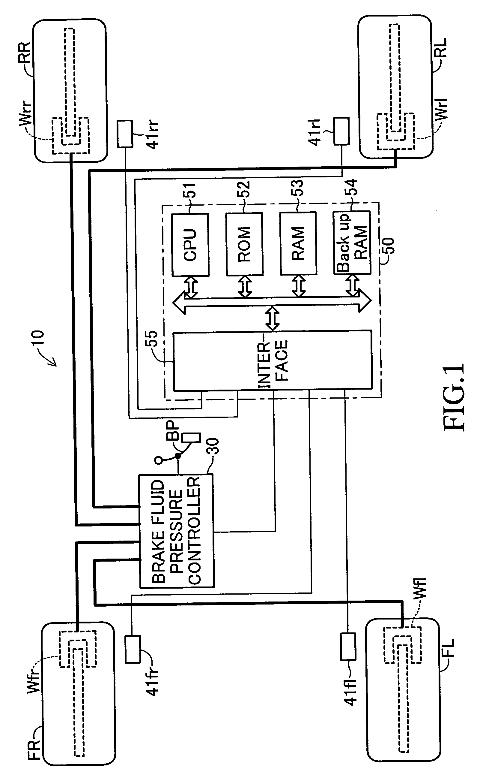
[0035]FIG. 1 schematically shows the structure of a vehicle equipped with a vehicle control apparatus 10 including a pump drive motor control apparatus according to a first embodiment of the present invention. The illustrated vehicle is a four-wheel, rear-wheel drive (FR) vehicle having two front wheels (a front left wheel FL and a front right wheel FR) which are non-drive wheels (follower wheels), and two rear wheels (a rear left wheel RL and a rear right wheel RR) which are drive wheels.

[0036]This vehicle control apparatus 10 has a brake fluid pressure controller 30 for generating a braking force in each wheel by means of brake fluid pressure.

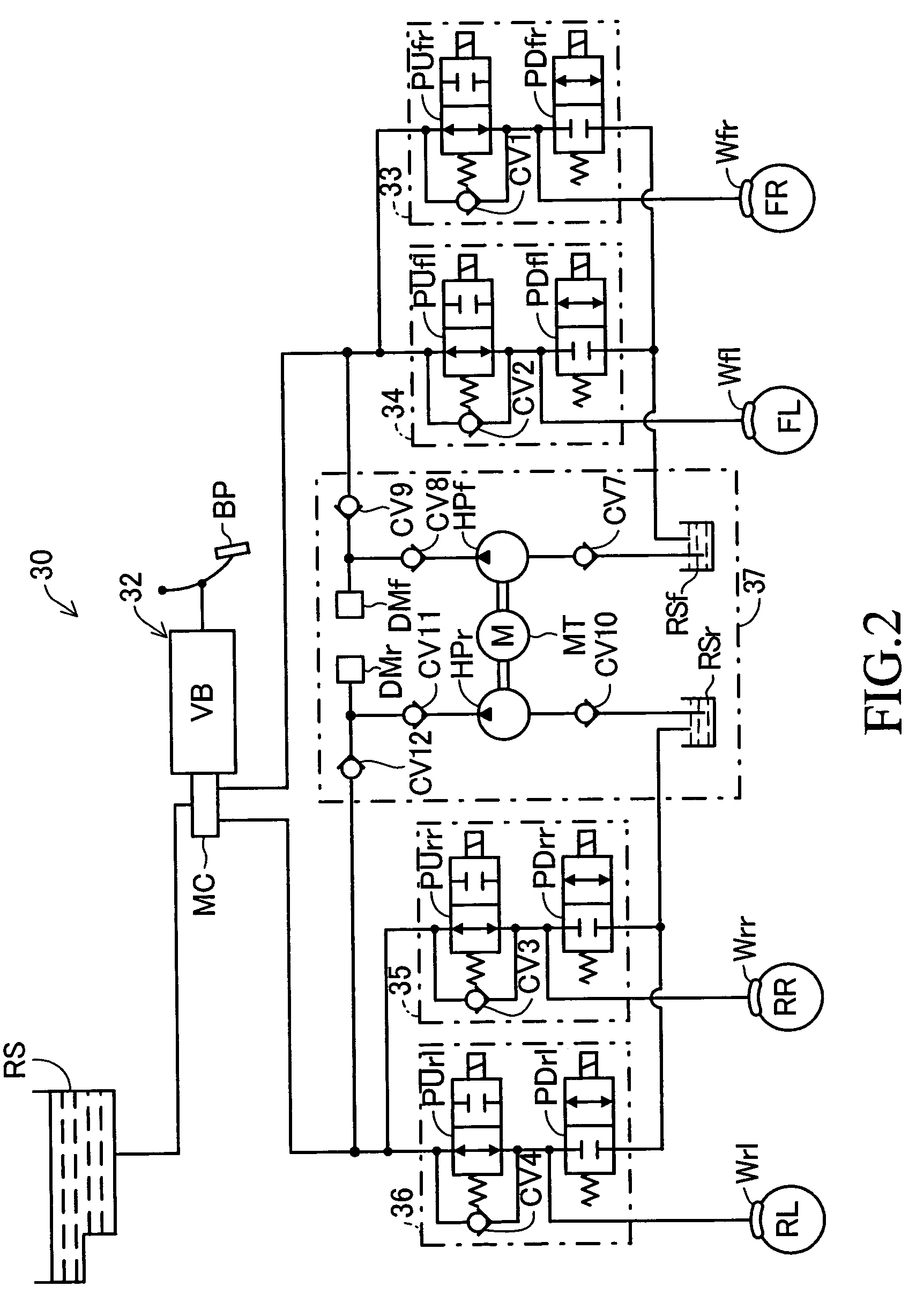
[0037]As schematically shown in FIG. 2, the brake fluid pressure controller 30 includes a brake fluid pressure generating section 32 which generates brake fluid pressure corresponding to the operating force of a brake pedal BP; an FR brake fluid pressure adjusting section 33, an FL brake fluid pressure adjusting section 34, an RR brake fluid ...

second embodiment

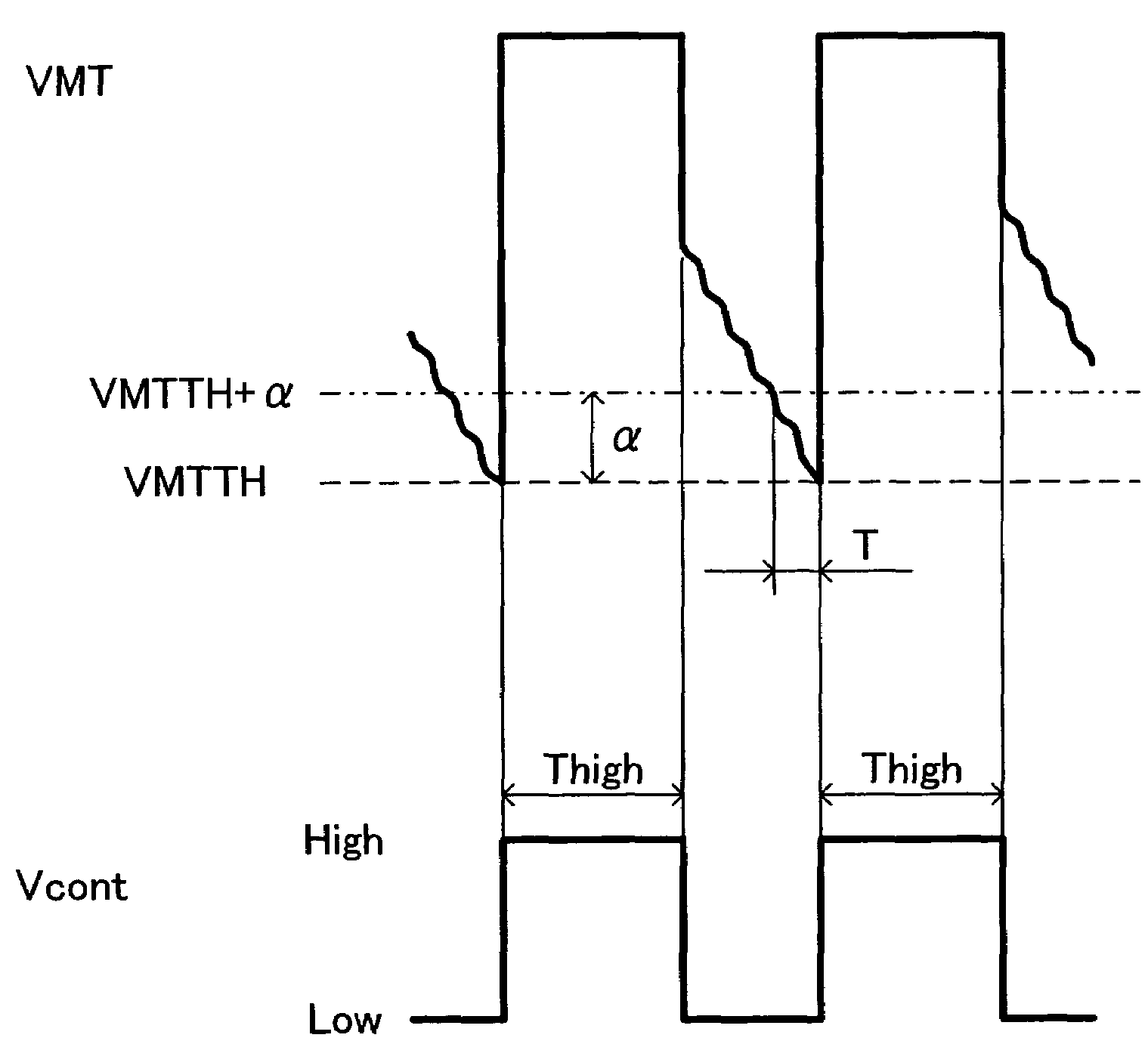
[0113]Next, a pump drive motor control apparatus according to a second embodiment of the present invention will be described. This apparatus differs from the first embodiment only in that when the loads imposed on the hydraulic pumps HPf and HPr are judged to be large (i.e., when the state in which the above-mentioned time T is not longer than a predetermined reference time Tth is successively detected the determination reference number of times Nth (3 times) or more), instead of increasing the High-level-maintenance time Thigh, the apparatus increases the voltage threshold VMTTH so as to increase the average rotational speed of the motor MT. Therefore, only this difference will be described.

Outline of Rotational Speed Control for Motor MT

[0114]Like the apparatus of the first embodiment, so long as the above-mentioned pump drive-control condition is satisfied, the present apparatus measures the above-mentioned time T (see FIG. 4) every time the supply of electricity of the motor MT ...


PUM


Abstract

A pump drive motor control apparatus controls a motor used for driving a hydraulic pump. Every time the supply of electricity to the motor is resumed (every time the motor control signal changes from a low level to a high level), the apparatus measures a time which the voltage generated by the motor requires to decrease by a predetermined amount, the time indicating the decreasing speed of the generated voltage. The apparatus normally sets the high-level maintenance time, in which the motor control signal is maintained high, to a base time. When a state in which the measured time is not longer than a reference time is detected a predetermined number of times (3 times) or more, the apparatus determines that the load of the pump is heavy. In such a case, the apparatus increases the average rotational speed of the motor by increasing the high-level maintenance time.

Description

BACKGROUND OF THE INVENTION[0001]1. Field of the Invention[0002]The present invention relates to a pump drive motor control apparatus for controlling the rotational speed of a motor for driving a pump, and more particularly to a pump drive motor control apparatus which controls the rotational speed of a motor through on-off control performed such that supply of electricity to the motor is resumed on the basis of a result of comparison between a predetermined threshold and a voltage which the motor generates during a period in which supply of electricity to the motor is stopped, and such that the supply of electricity is stopped after the supply of electricity is continued for a predetermined period of time.[0003]2. Description of the Related Art[0004]A conventional pump drive motor control apparatus of such a type is disclosed in, for example, Japanese kohyo (PCT) Patent Publication No. 2002-506406. The disclosed apparatus is applied to a motor for driving a hydraulic pump which pum...

Claims


Application Information

Patent Timeline
Patent Type & Authority Patents(United States)
IPC IPC(8): B60T13/20B60T8/48B60T17/02F04B49/06H02P7/29H02P7/291
CPCB60T17/02F04B49/065F04B2203/0209F04B2203/0202
Inventor KOKUBO, KOICHI
Owner ADVICS CO LTD
Why Eureka
Try Eureka