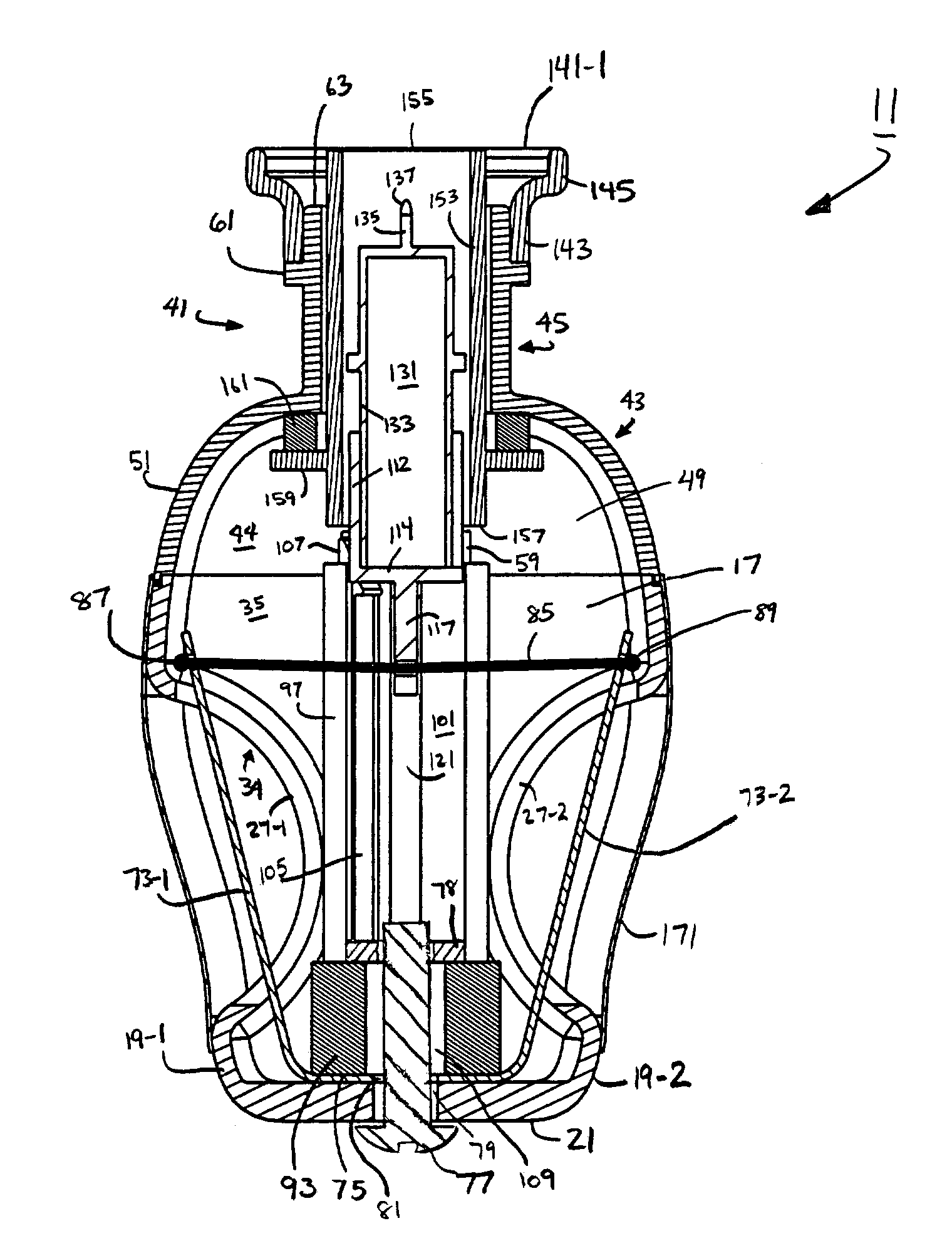
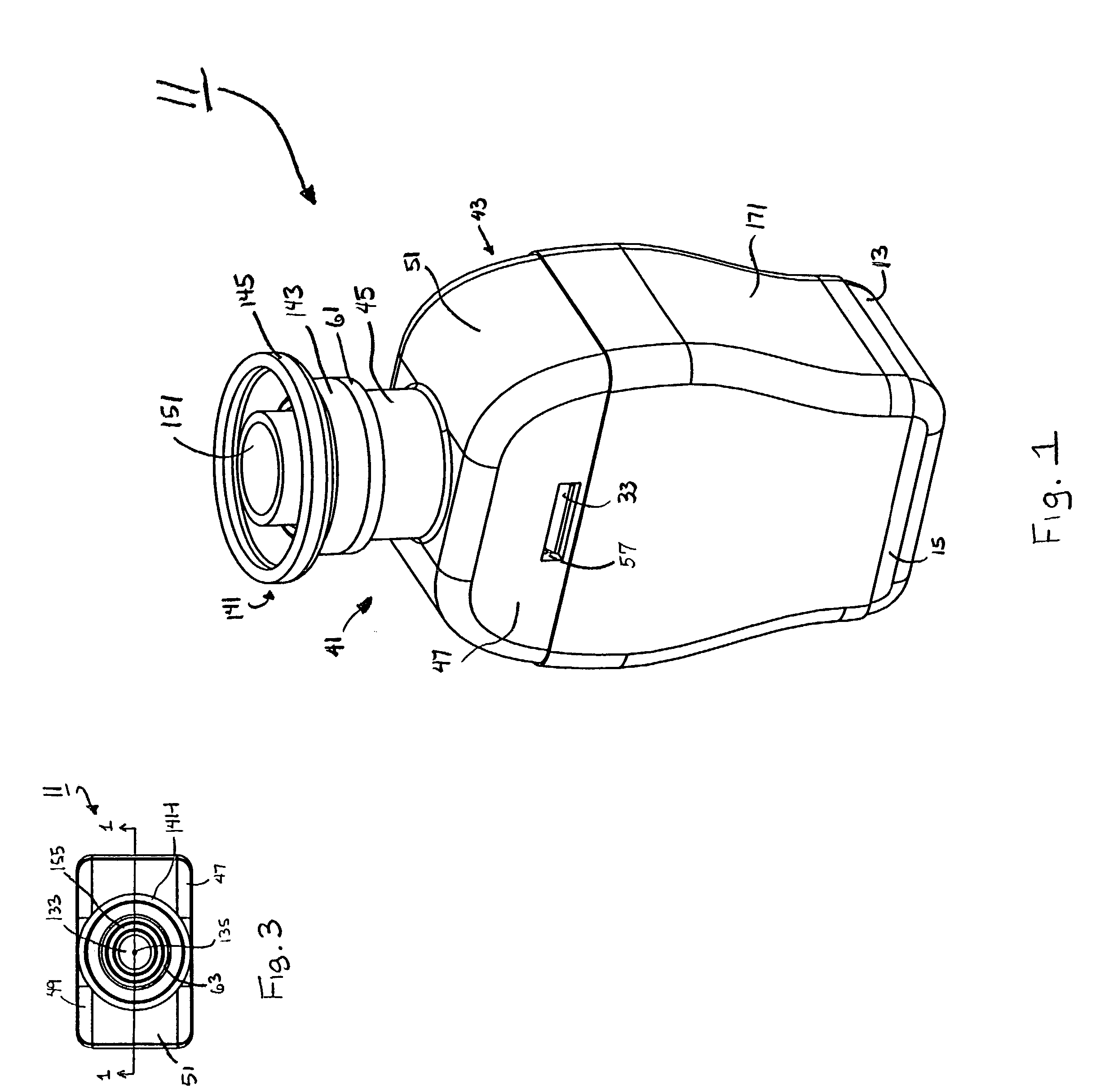
[0036]Referring now to FIGS. 1 through 5, there are shown various views of one embodiment of a lancet device constructed according to the teachings of the present invention, said lancet device being shown in an uncocked state and being represented generally by reference numeral 11.
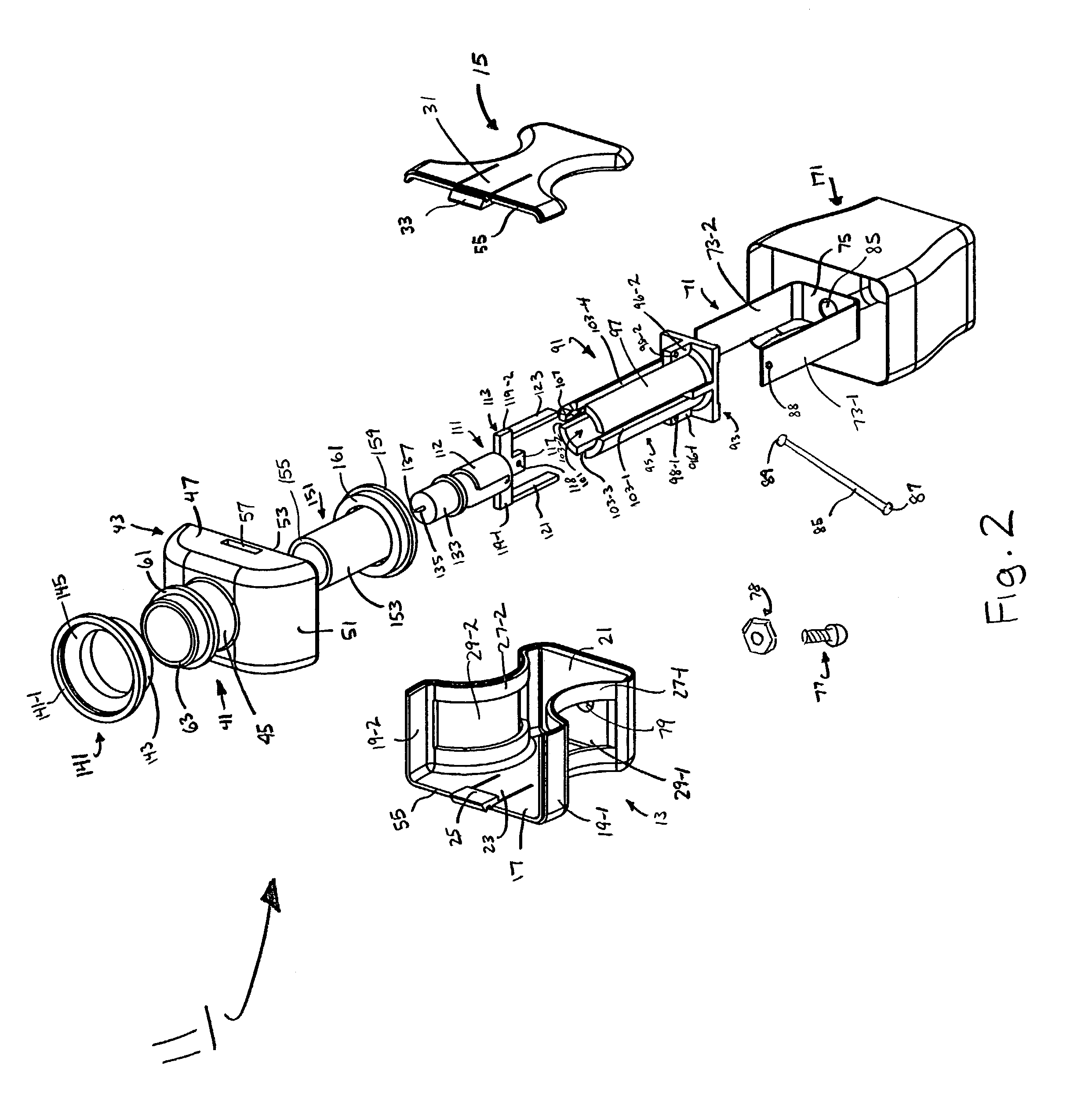
[0037]Device 11 includes a rear base portion 13 and a front base portion 15. Rear base portion 13, which is also shown separately in FIG. 6, is a unitary structure, preferably made of a durable molded plastic or similarly suitable material, and comprises a rear wall 17, a pair of side walls 19-1 and 19-2, a bottom wall 21, an open front and an open top. Rear wall 17 is shaped to include an upwardly extending tab 23, tab 23 terminating at its top end in a rearwardly facing pawl 25. For reasons to become apparent below, tab 23 is adapted to be resiliently flexed forwardly.
[0038]A scalloped portion 27-1 is provided in side wall 19-1, and a corresponding scalloped portion 27-2 is provided in side wall 19-2. As will be described below, scalloped portions 27-1 and 27-2 are adapted to receive a user's thumb and forefinger, respectively (or vice versa). Scalloped portion 27-1 is provided with a longitudinal slot 29-1, and scalloped portion 27-2 is provided with a corresponding longitudinal slot 29-2, the functions of slots 29-1 and 29-2 to become apparent below.
[0039]Front base portion 15, which is also shown separately in FIG. 7, is a unitary structure, preferably made of the same material as rear base portion 13. Front base portion 15 has a shape that is substantially a mirror image of rear wall 17. As such, front base portion 15 is shaped to include an upwardly extending resilient tab 31, tab 31 terminating at its top end in an forwardly facing pawl 33. Front base portion 15 is fitted together with rear base portion 13, for example by mating peripheral edges, to jointly define a hollow base 34 having a base cavity 35.
[0040]Device 11 also includes a cover 41. Cover 41, which is also shown separately in FIG. 8, is a unitary structure, preferably made of a durable molded plastic or similarly suitable material, and comprises a bottom portion 43 and a top portion 45. Bottom portion 43, which is generally trough-shaped and defines an interior cavity 44, includes a front wall 47, a rear wall 49, an upwardly-curved intermediate wall 51 and an open bottom. Bottom portion 43 sits upon base 34, with the bottom edge 53 of bottom portion 43 being appropriately dimensioned to substantially match the top edge 55 of base 34. A transverse slot 57 is provided in front wall 47, and a corresponding transverse slot 59 is provided in rear wall 49, slot 57 receiving pawl 33 and slot 59 receiving pawl 25. In this manner, cover 41 is secured to base 34. To remove cover 41 from base 34, one flexes tab 31 rearwardly to remove pawl 33 from slot 57 and/or flexes tab 23 forwardly to remove pawl 25 from slot 59.
[0041]Top portion 45, which is generally tubular in shape and open at both ends, extends upwardly from intermediate wall 51. An external circumferential flange 61, the purpose of which will be described below, is provided on top portion 45 a short distance below its top end 63.
[0042]Base 34 and cover 41 jointly define a hollow body.
[0043]Device 11 additionally comprises a biasing member 71 disposed within base 34. Biasing member 71, which is also shown separately in FIG. 9, is a unitary U-shaped ribbon-type structure, made of spring steel or the like, and comprises a pair of resilient, outwardly-biasing arms 73-1 and 73-2 interconnected by a base portion 75. Arms 73-1 and 73-2, the free ends of which are adapted to be pivoted towards one another by a user for reasons to become apparent below, are aligned with and accessible through slots 29-1 and 29-2, respectively. Base portion 75 is fixed to the top of bottom wall 21 of rear base portion 13 by a screw 77 and a nut 78, screw 77 being inserted through transverse openings 79 and 81 provided in bottom wall 21 and base portion 75, respectively.
[0044]Device 11 further comprises a flexible filament 85 disposed within base 34. Filament 85, which may be a length of string or another similarly suitable material, is a unitary structure having a first end 87 and a second end 89. First end 87 is inserted through a transverse opening 88 formed in arm 73-1 proximate to its free end, first end 87 being knotted to prevent its withdrawal through opening 88. Second end 89 is inserted through a transverse opening 90 formed in arm 73-2 proximate to its free end, second end 89 being knotted to prevent its withdrawal through opening 90. For reasons to become apparent below, the length of filament 85 is such that, when the free ends of arms 73-1 and 73-2 are pivoted towards one another (i.e., when device 11 is cocked), slack is created in filament 85, and when the free ends of arms 73-1 and 73-2 are nearly at their relaxed positions (i.e., when device 11 is uncocked), filament 85 is pulled taut.
[0045]It should be understood that, although biasing member 71 and filament 85 are described in the present embodiment as separate structures, biasing member 71 and filament 85 could be modified to be a unitary structure.
[0046]Device 11 also includes a support member 91. Support member 91, which is also shown separately in FIG. 10, is a unitary structure, made of a durable molded plastic or another similarly suitable material, and comprises a base portion 93 and a stem portion 95. Base portion 93, which is generally rectangular in shape, is seated on top of base portion 75 of biasing member 71.
[0047]Stem portion 95, which extends upwardly from base portion 93, is shaped to include a pair of tabs 96-1 and tabs 96-2 and a generally cylindrical member 97. Tabs 96-1 and 96-2 flank cylindrical member 97, with tab 96-1 facing rear wall 17 of rear base portion 13 and tab 96-2 facing front wall 15. For reasons to become apparent below, tab 96-1 is provided with a transverse opening 98-1, and tab 96-2 is provided with a transverse opening 98-2.
[0048]Cylindrical member 97, which is open at its top end, is shaped to include a longitudinally-extending bore 101 and a plurality of longitudinally-extending transverse slots 103-1, 103-2, 103-3 and 103-4 communicating with bore 101. Slots 103-1 and 103-2 are aligned with slots 29-1 and 29-2, respectively, of rear base portion 13 and permit filament 85 to pass through cylindrical member 97. For reasons to become apparent below, slot 103-3 is aligned with tab 96-1, and slot 103-4 is aligned with tab 96-2.
[0049]Cylindrical member 97 is also shaped to include an arm 105, arm 105 being biased radially inwardly towards bore 101. The top end of arm 105, which extends just beyond the top end of bore 101, is shaped to include a releasable catch or pawl 107, the purpose of which will be described below.
[0050]Support member 91 is fixed to biasing member 71 by screw 77 and nut 78, screw 77 being inserted through a bore 109 in support member 91 that is aligned with transverse openings 79 and 81 in bottom wall 21 and base portion 75, respectively. (Instead of being secured to one another by screw 77 and nut 78, support member 91 and biasing member 71 may be secured together by other means, such as by being molded together, by being coupled together by a snap feature, etc.)
[0051]Device 11 also includes a lancet holder 111, lancet holder 111 being slidably mounted in cylindrical member 97 of support 91. Lancet holder 111, which is also shown separately in FIG. 11, is a unitary structure, made of a durable molded plastic or another similarly suitable material, and comprises a top portion 112 and a bottom portion 113. Top portion 112 is a generally tubular structure having a closed bottom end 114 and an open top. Bottom portion 113, which is generally T-shaped, includes a downwardly extending central arm 117 and a pair of laterally extending side arms 119-1 and 119-2. Central arm 117, which is disposed within bore 101 of cylindrical member 97, is provided with a transverse opening 118 aligned with slots 103-1 and 103-2. For reasons to be described below, filament 85 extends through opening 118.
[0052]Side arm 119-1 extends through slot 103-3 and is provided with a transverse opening 120-1. One end of an elastic strap 121 is secured to arm 119-1, and the opposite end of strap 121 is secured to tab 96-1. Preferably, strap 121 is formed by overmolding (or “two-shot molding”) a thermoplastic clastomeric (“TPE”) material over arm 119-1 and through opening 120-1 and by overmolding (or “two-shot molding”) the same TPE material over tab 96-1 and through opening 98-1. (Alternatively, instead of interconnecting arm 119-1 and tab 96-1 using strap 121, one could insert a first end of an elastic filament through opening 120-1 and insert a second end of said elastic filament through opening 98-1, said first and second ends of said elastic filament being knotted to prevent their withdrawal through opening 120-1 and opening 98-1, respectively.)
[0053]Side arm 119-2 extends through slot 103-4 and is provided with a transverse opening 120-2. One end of an elastic strap 123 is secured to arm 119-2, and the opposite end of strap 123 is secured to tab 96-2. Preferably, strap 123 is formed by overmolding (or “two-shot molding”) a TPE material over arm 119-2 and through opening 120-2 and by overmolding (or “two-shot molding”) the same TPE material over tab 96-2 and through opening 98-2. (Alternatively, instead of interconnecting arm 119-2 and tab 96-2 using strap 123, one could insert a first end of an elastic filament through opening 120-2 and insert a second end of said elastic filament through opening 98-2, said first and second ends of said filament being knotted to prevent their withdrawal through opening 120-2 and opening 98-2, respectively.)
[0054]Elastic straps 121 and 123 are used to bias lancet holder 111 downwardly; however, the biasing strength of biasing member 71 is greater than the biasing strength of straps 121 and 123. Accordingly, in the absence of a compressive or inwardly-directed force applied to biasing member 71 by a user, filament 85 is pulled taut by biasing member 71, causing holder 111 to be positioned at a relatively high position within support 91 and stretching straps 121 and 123 well beyond their normal or relaxed lengths (but not to their rupturing points). If, however, a compressive force is applied to biasing member 71 by a user, slack is created in filament 85, and straps 121 and 123 are permitted to contract towards their relaxed lengths, causing holder 111 to be pulled down within support 91. Once sufficient compressive force has been applied to biasing member 71 to draw the top of holder 111 down below pawl 107, further compressive force need not be applied to maintain biasing member 71 in a compressed state as pawl 107 pivots inwardly to engage the top of holder 111. The energy stored in the thus compressed biasing member 71 may thereafter be released by removing pawl 107 from holder 111 in the manner to be described below. As can be appreciated, once the restraint on biasing member 71 is released, biasing member 71 expands towards its relaxed state, causing holder 111 to quickly move upwardly relative to support 91. Elastic straps 121 and 123, which are then highly stretched by the quick upward movement of holder 111, provide a small degree of downward spring to holder 111.
[0055]Device 11 additionally includes a lancet 131. Lancet 131, which may be a conventional, disposable lancet, is a unitary member, preferably made of metal or another similarly suitable material. Lancet 131 comprises a cylindrical base 133 and a stem 135. Base 133 is removably received within top portion 112 of holder 111. Stem 135 of lancet 131 extends upwardly from base 133 and terminates in a sharp tip 137 adapted to pierce the skin of a patient.
[0056]Device 11 further includes a seal 141. Seal 141, which may be made of silicone rubber or a similarly suitable material, is a unitary structure comprising a lower portion 143 and an upper portion 145. Lower portion 143 is tubular in shape and is inserted over top portion 45 of cover 41, with the bottom edge of lower portion 143 resting upon flange 61 of top portion 45. Upper portion 145 extends beyond top portion 45 of cover 41 and flares outwardly for reasons to become apparent below.
[0057]Device 11 additionally includes an actuator 151, actuator 151 being slidably mounted within top portion 45 of cover 41. Actuator 151, which is also shown separately in FIG. 12, is a unitary structure, preferably made of a durable molded plastic or another similarly suitable material. Actuator 151 is shaped to include a cylindrical portion 153, cylindrical portion 153 having a top end 155 and a bottom end 157. Top end 155 is positioned at approximately the top edge 141-1 of seal 141, and bottom end 157 extends into bottom portion 43 of cover 41 and is aligned with and spaced a short distance above pawl 107, as well as the remainder of cylindrical member 97 of support 91.
[0058]An external circumferential flange 159 is formed on actuator 151 and is positioned a short distance from bottom end 157. A ring 161, which may be made of foam or a like material, is mounted on top of flange 159. The bottom surface of ring 161 is fixed at a first point to the top of flange 159 using a suitable adhesive (not shown), and the top surface of ring 161 is fixed at a second point, approximately 180 degrees from said first point, to the bottom surface of intermediate wall 51 of cover 41. In this manner, actuator 151 is biased upwardly by ring 161.
[0059]Device 11 further includes a protective membrane or skin 171 tightly fitted over base 34 (except for the bottom portion thereof) and the exposed portions of biasing member 71. Skin 171 is preferably made of a flexible, elastic material.
[0060]In use, an operator grips device 11 with the forefinger and the thumb of one hand, the forefinger being positioned against that portion of skin 171 covering scalloped portion 27-1 of base 34 and the thumb being positioned against that portion of skin 171 covering scalloped portion 27-2 of base 34 (or vice versa). At this point, prior to any cocking of device 11, device 11 is essentially as shown in FIGS. 1 through 5. The operator then cocks device 11 by compressing spring 71 with the forefinger and the thumb and then by releasing pressure from spring 71 while still maintaining a hold on device 11. As noted above, the compression of spring 71 causes the free ends of arms 73-1 and 73-2 to be pivoted towards one another and causes lancet holder 111 to be drawn down below pawl 107. The subsequent release of compression on spring 71 by the operator then causes lancet holder 111 to come into engagement with pawl 107, pawl 107 retaining holder 111 in place. At this point, device 11 is cocked and is essentially as seen in FIGS. 13 through 15. It can readily be appreciated that, with spring 71 thus restrained from returning to its relaxed state by the engagement of pawl 107 with holder 111, a considerable amount of potential energy is stored in spring 71. Device 11 is then used by pressing top edge 141-1 of seal 141 and top end 155 of actuator 151 against that portion of the patient where sampling is desired. As top edge 141-1 of seal 141 is pressed against the skin of the patient (and is engaged therewith), top edge 141-1 expands in diameter, stretching the engaged skin outwardly. Concurrently, as top end 155 of actuator 151 engages the skin of the patient, top end 155 causes distension of the skin and, at the same, causes actuator 151 to be moved downwardly. Continued movement of actuator 151 causes bottom end 157 of actuator 151 to move pawl 107 out of engagement with lancet holder 111, thereby resulting in the release of potential energy stored by spring 71 and the firing of lancet 131 into the patient.
[0061]Once device 11 has been used to pierce the skin of a patient, lancet 131 should be replaced. To access a used lancet 131 disposed within the body of device 11, a user depresses tabs 23 and/or 31 until cover 41 can be unhooked from base 34. The used lancet 131 may then be removed from holder 111 and replaced with a new lancet 131. After a new lancet 131 has been placed in holder 111, cover 41 may then be re-attached to base 34.
[0062]As noted above, one desirable property of device 11 is that device 11 is not limited to use on a finger but may be used on alternate sites of a patient.
[0063]In another embodiment (not shown), skin 171 is replaced with a rigid protective casing that encloses base 34 and the exposed portions of biasing member 71, the device further including a pair of depressable buttons, each button having a first end coupled to a respective arm 73 of biasing member 71 and a second end extending through the protective casing.
[0064]The embodiments of the present invention described above are intended to be merely exemplary and those skilled in the art shall be able to make numerous variations and modifications to it without departing from the spirit of the present invention. All such variations and modifications are intended to be within the scope of the present invention as defined in the appended claims.