Integrated channel filter using multiple resonant filters and method of operation

a filter and integrated channel technology, applied in the field of signal processing, can solve the problem of tending to corrupt all of the channels in the input signal, and achieve the effect of substantially reducing the disadvantages and eliminating the problems of prior amplifiers

Active Publication Date: 2007-12-04
CSR TECH INC
View PDF21 Cites 16 Cited by
  • Summary
  • Abstract
  • Description
  • Claims
  • Application Information

AI Technical Summary

Benefits of technology

[0003]In accordance with the present invention, the disadvantages and problems associated with prior amplifiers have been substantially reduced or eliminated.
[0005]The following technical advantages may be achieved by some, none, or all of the embodiments of the present invention.
[0007]By adjusting the capacitances of the two resonant filters, such that their resonant frequencies are aligned with each other, a sharper bandpass filter response is achieved. In effect, the quality factor of the filters and the amplifier are higher than alternative circuits with only a single tunable resonant filter. This results in higher gain and greater channel selectivity by the circuit.

Problems solved by technology

This reflection of undesired channels tends to corrupt all of the channels in the input signal, including the desired channels.

Method used


Image

  • Integrated channel filter using multiple resonant filters and method of operation
  • Integrated channel filter using multiple resonant filters and method of operation
  • Integrated channel filter using multiple resonant filters and method of operation

Examples


Embodiment Construction

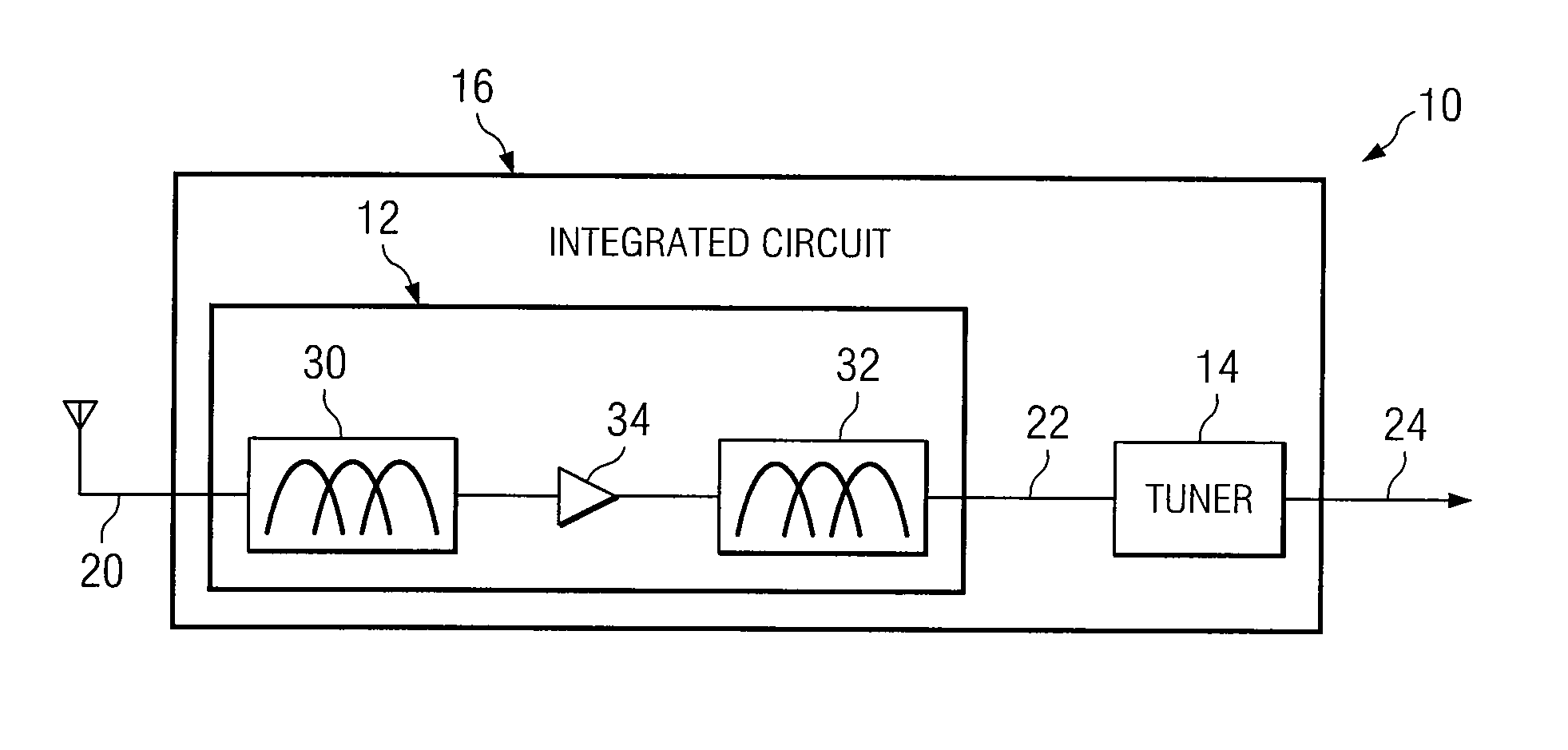
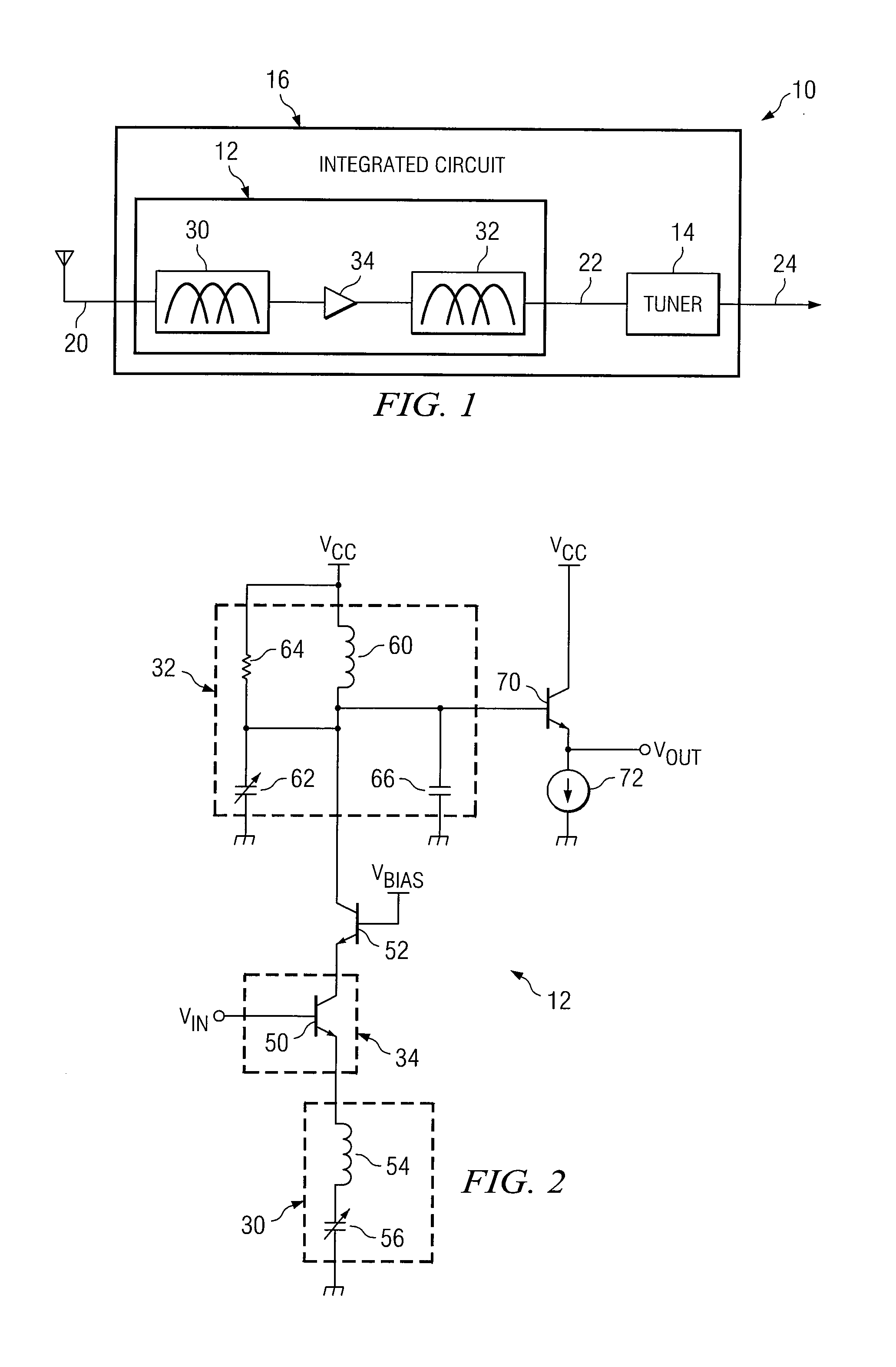
[0014]FIG. 1 illustrates one embodiment of a system 10 that includes a pre-select amplifier circuit 12 coupled to a tuner 14. At least portions of circuit 12 and tuner 14 are formed on an integrated circuit 16. In general, circuit 12 receives an input signal 20 comprising a plurality of frequency channels. Circuit 12 filters and amplifies signal 20 for communication to tuner 14 as signal 22. Tuner 14 receives signal 22 and communicates output signal 24. In general, circuit 12 can achieve a higher gain and greater channel selectivity of signal 20 because it includes two resonant filter circuits 30 and 32 that are tuned to substantially the same resonant frequency.

[0015]Circuit 12 comprises first filter 30 and second filter 32 coupled to amplifier 34. Filters 30 and 32 comprise any suitable number and combination of frequency selective components that may be formed on integrated circuit 16. In a particular embodiment described in greater detail with reference to FIG. 2, filter 30 comp...


PUM


Abstract

A circuit includes a first filter comprising a first inductor coupled to a first variable capacitor, wherein the first filter is associated with a first resonant frequency. The circuit further comprises an amplifier coupled to the first filter and a second filter coupled to the amplifier. The second filter comprises a second inductor coupled to a second variable capacitor, wherein the second filter is associated with a second resonant frequency that is substantially the same as the first resonant frequency. At least a portion of the first filter and at least a portion of the second filter are formed on an integrated circuit.

Description

TECHNICAL FIELD OF THE INVENTION[0001]This invention relates in general to signal processing, and more particularly to an integrated channel filter using multiple resonant filters.BACKGROUND OF THE INVENTION[0002]It is desired to have a low noise amplifier (LNA) with a bandpass filter response and adjustable center frequency. A single resonant filter in the emitter leg of the LNA is not adequate due to the presence of an additional resonance caused by a collector load inductor and parasitic capacitances. The resonance in the collector leg of the LNA does not necessarily occur at the same frequency as the resonance in the emitter filter, and therefore causes an undesirable broadening of the bandpass filter response.SUMMARY OF THE INVENTION[0003]In accordance with the present invention, the disadvantages and problems associated with prior amplifiers have been substantially reduced or eliminated.[0004]In accordance with one embodiment of the present invention, a circuit includes a firs...

Claims


Application Information

Patent Timeline
Patent Type & Authority Patents(United States)
IPC IPC(8): H03K5/00
CPCH03F1/22H03F3/50H03H7/12H03H11/1213H03J3/20H04B1/28H04B1/30H03F3/19H03F2203/5031H03F2200/108H03F2200/294H03F2200/411H03F2200/489H03F2200/501H03H11/1291H03J2200/10H03H7/1758H03H7/06H03H3/08H03H9/54
Inventor HISAYASU, PHILIP T.WOMAC, MICHAEL D.
Owner CSR TECH INC
Why Eureka
Try Eureka