Axial loading management in turbomachinery

a technology of axial loading and turbomachinery, which is applied in the direction of liquid fuel engines, vessel construction, marine propulsion, etc., can solve the problems of premature failure, increased actuation response time, and axial loading on the components, so as to reduce the axial load on the unison ring and reduce the axial load

Active Publication Date: 2007-12-11
GARRETT TRANSPORATION I INC
View PDF16 Cites 8 Cited by
  • Summary
  • Abstract
  • Description
  • Claims
  • Application Information

AI Technical Summary

Benefits of technology

[0007]Vanes of this invention are included within a turbocharger having variable nozzle geometries. The vanes are oriented to direct exhaust gas to a turbine and are arranged within the turbine housing between a nozzle wall and a unison ring, which actuates the vanes. The unison ring receives an axial load exerted by the vanes and the exhaust gas passing between the vanes. In one aspect, each of the vanes comprises two axial surfaces that are on opposite sides of the vane. The opposite axial surfaces include two corresponding chambers. These chambers are partially exposed to each other through an aperture. This aperture equalizes the pressures in the chambers and, thereby, reduces the axial load on the unison ring.
[0008]In another aspect, each of the vanes includes two opposite airfoil surfaces. At least one of the airfoil surfaces includes a notch that allows a chamber in the cavity of the vane to be pressurized by the exhaust gas. The pressure in the cavity creates a counteracting force that reduces the axial load on the unison ring.

Problems solved by technology

These differential gas pressures inside the turbine housing often lead to axial loading on the components.
Excessive axial loading can cause increased friction between the components, which will lead to increased actuation response time and premature failure due to excessive wear.

Method used


Image

  • Axial loading management in turbomachinery
  • Axial loading management in turbomachinery
  • Axial loading management in turbomachinery

Examples


Embodiment Construction

[0020]Various exemplary methods, devices, systems, arrangements, etc., disclosed herein address issues related to technology associated with turbochargers.

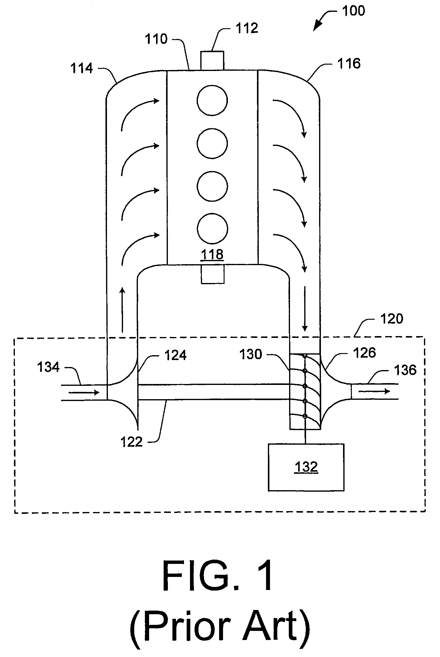
[0021]Turbochargers are frequently utilized to increase the output of an internal combustion engine. Referring to FIG. 1, an example system 100, including an example internal combustion engine 110 and an example turbocharger 120, is shown. The internal combustion engine 110 includes an engine block 118 housing one or more combustion chambers that operatively drive a shaft 112. As shown in FIG. 1, an intake port 114 provides a flow path for air to the engine block while an exhaust port 116 provides a flow path for exhaust from the engine block 118.

[0022]The exemplary turbocharger 120 acts to extract energy from the exhaust gas and to provide energy to intake air, which may be combined with fuel to form combustion gas. As shown in FIG. 1, the turbocharger 120 includes an air inlet 134, a shaft 122, a compressor 124, a turbine 126, a...


PUM


Abstract

Exemplary vanes for a turbocharger having variable nozzle geometries are disclosed. In one aspect, each of the vanes includes two axial surfaces that are on opposite sides of the vane. The opposite axial surfaces include two corresponding chambers. These chambers are partially exposed to each other through an aperture. Such an aperture allows for some degree of equalization of the pressures in the chambers and, thereby, reduces the axial load exerted by a vane, for example, on the unison ring. In another aspect, each of the vanes includes two opposite airfoil surfaces. At least one of the airfoil surfaces includes a notch that allows a chamber in the nozzle to be pressurized by the exhaust gas. The pressure in the chamber creates a counteracting force that reduces the axial load exerted by a vane.

Description

TECHNICAL FIELD[0001]Subject matter disclosed herein relates generally to turbomachinery and, more particularly, to the management of axial loading in turbochargers.BACKGROUND[0002]To achieve higher efficiency and output, some internal combustion engines use turbochargers to pressurize intake air. A turbocharger typically includes a compressor and a turbine, which are mechanically mounted onto a common shaft. The turbine extracts power from the heat and volumetric flow of the exhaust gas exiting the engine and the compressor applies the power to compress the intake air going into the engine. Specifically, the exhaust gas exiting the engine is routed into a turbine housing of a turbocharger in a manner that causes the turbine to spin. Since the compressor and the turbine are linked by the common shaft, the rotary action of the turbine causes the compressor to spin and pressurize the intake air to the engine.[0003]Controlling the flow of exhaust gas to the turbine can improve the effi...

Claims


Application Information

Patent Timeline
Patent Type & Authority Patents(United States)
IPC IPC(8): F02D23/00F04D29/38F04D29/44F04D29/56B63H1/26B63H7/02F04D29/46
CPCF04D29/462F02B37/24F01D17/165F05D2220/40
Inventor KUSTER, KURT W.
Owner GARRETT TRANSPORATION I INC
Why Eureka
Try Eureka