Cable locating device

a technology of locating device and cable, which is applied in the direction of measuring device, resistance/reacting/inhibiting, instruments, etc., to achieve the effect of convenient us

Inactive Publication Date: 2007-12-11
PORCU GREGORY +1
View PDF14 Cites 23 Cited by
  • Summary
  • Abstract
  • Description
  • Claims
  • Application Information

AI Technical Summary

Benefits of technology

[0014]The device herein disclosed and described provides an easily employed cable identification device that allows for the quick determination of the identity of cable terminating at one end with reference to a termination point in an office or room of a building at the other end. The device as described and disclosed does not require special adapters for different types of cables being identified and does not require that the distal end of the cable be stripped of insulation for engagement to the device. Additionally, the device neither requires the installer in the switch room to hold any electronic devices while locating and labeling the cables, nor any electronic transmission devices to be employed by the second person in the remote room at the other end of the cable.
[0015]Still further, the device provides for visual identification of the individual cables using lights rather than audible identification using transmitted signals. Elimination of transmission of electronic audible tones provides the additional advantage of eliminating false signals on other directly adjacent cables and the resulting misidentification of cables. Using the device with individual visual identification of one of a plurality of device-engaged cables also allows the installer in the switch room to handle individual cables only twice, rather than sifting through a whole bundle of hundreds of cables each time a signal is sent from a remote location.
[0019]During a cable identification session, a user in the switch room inserts one end of a stripped or unstripped cable into one of the plurality of tubes and connects to the AC ground socket in a switch room. The other person, located in the remote building room, connects one end of the engagement cable to the ground socket in a remote room and plugs the other end, adapted to the sockets engaged with cables in the room, into one of the sockets. This closes the circuit to provide power to the LED or light adjacent to one of the many cables engaged into one of the plurality of tubes. As a result, a visual cue is provided as to the correct cable, out of the many engaged with the device, when the LED adjacent to the connected cable lights up. The person in the switch room can then properly label the identification of the connected cable. In a preferred option to the device, a second means to electrically connect the tube to a cable is provided in the form of conducting fibers such as steel wool located adjacent to the bottom of the tube and around the pin. This provides a second means to electrically engage the distal end of the cable in the switch room without the need to strip the insulation, since the distal ends of all strands of the cable are exposed and will make contact with the conducting fibers.
[0021]An object of this invention is to provide a device to allow for visual identification of individual cables being identified without the need to sift through the cables one-by-one.
[0023]An additional object of this invention is the provision of such a cable identification device which eliminates the need to strip the distal ends of the cables being identified.
[0024]A further object of this invention is the provision of a cable identification device that allows a user to engage a plurality of cables concurrently and then identify one cable visually from that plurality.

Problems solved by technology

Additionally, the device neither requires the installer in the switch room to hold any electronic devices while locating and labeling the cables, nor any electronic transmission devices to be employed by the second person in the remote room at the other end of the cable.

Method used


Image

  • Cable locating device
  • Cable locating device
  • Cable locating device

Examples


Embodiment Construction

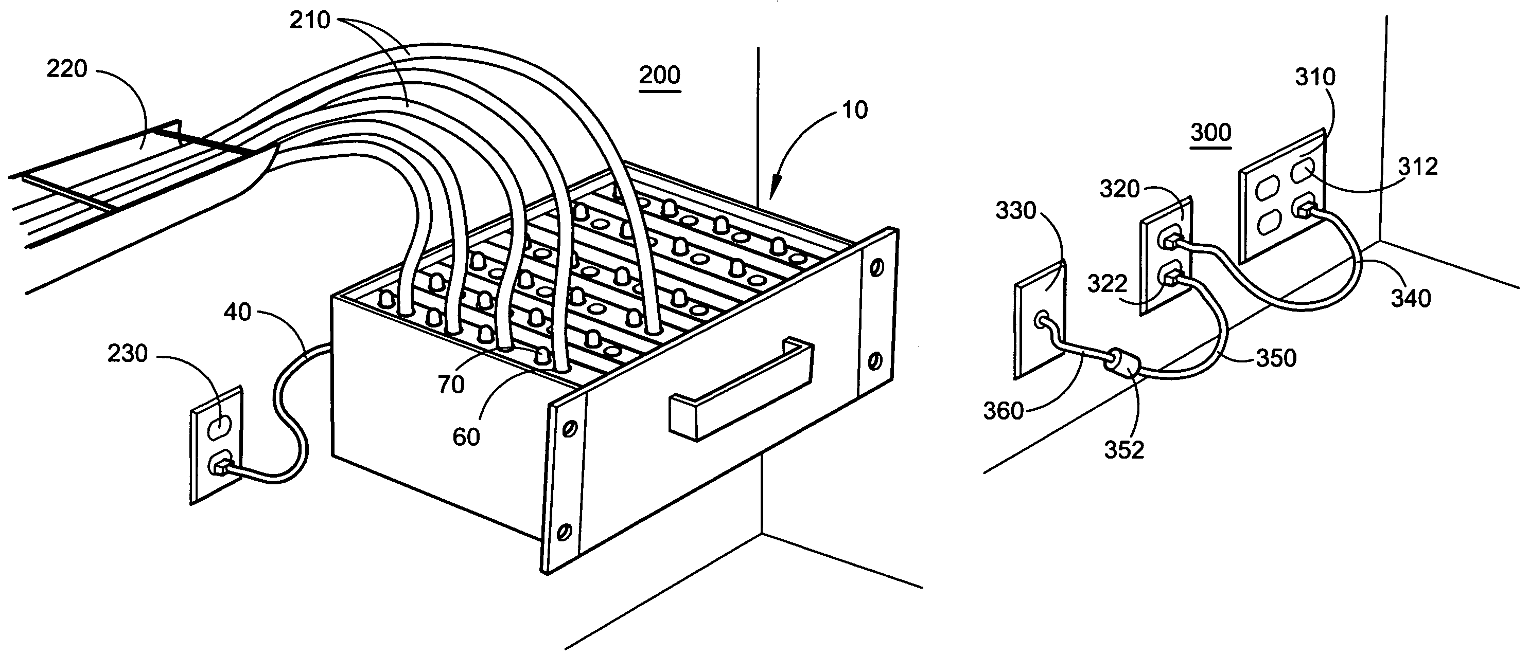
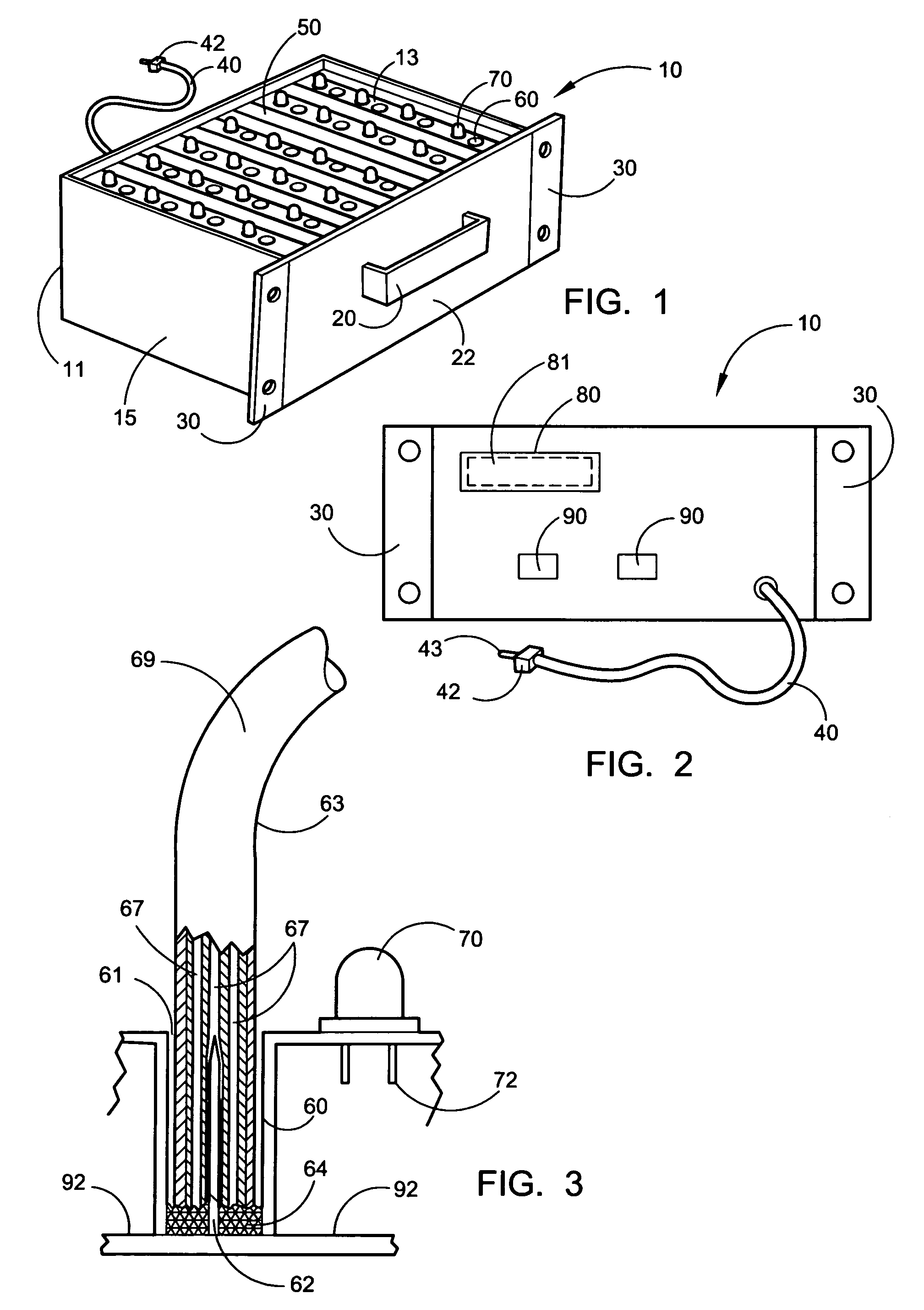
[0036]Referring now to the drawings FIGS. 1 through 8, wherein similar parts are identified by like reference numerals, there is seen in FIG. 1 a front perspective view of the cable locating device 10. Cable locating device 10 can be placed in a switch room on a table, shelf, or adapted for mounting in a conventional telecommunications relay rack. Cable locating device 10 is preferably a rectangularly shaped case 11 having an upper surface 13 surrounded by a sidewall 15. A carrying handle 20 may be provided and engaged with one surface such as the front surface 22 for easy transport. For ease of engagement with existing network equipment in a switch room, mounting brackets 30 located adjacent to front surface 22 can be provided. However, the device 10 will also function sitting on the floor or a table.

[0037]Means for electrical engagement of the device 10 with the ground circuit of an AC electrical system of a building is provided by grounding wire 40 extending from the device to an...


PUM


Abstract

A device for identifying individual cables communicating between many remote locations to one central location using the building AC ground circuit to communicate between the remote location and the central location. The device includes a plurality of tubes adapted to engage individual cables and corresponding light-emitting diodes (LED) adjacent to each tube. A needle in the tube provides communication with the wire of the insulated cable. A remote interconnection cable provides connection between cable remote ends, and the building ground circuit concurrently providing a means to prevent engagement with the energized AC circuits.

Description

PRIORITY[0001]This application claims the benefit of U.S. Provisional Application Ser. No. 60 / 679,071, filed on May 9, 2005.BACKGROUND OF THE INVENTION[0002]1. Field of the Invention[0003]The invention relates to the field of telecommunications and computer network cabling installations. More particularly, the preferred embodiment of the present invention relates to a device employed to identify various types of telecommunication and networking cables communicating from remote areas of an office or other building to a switch room within an office or building. Such identification is provided without the need to strip the distal ends of the wires or cables.[0004]2. Description of the Related Art[0005]Along with the boom of the Internet, the demand for telecommunications and computer networking infrastructure has also increased at a rapid rate. In commercial buildings and office buildings in particular numerous cables are often needed to connect the phone, computer, video, control, int...

Claims


Application Information

Patent Timeline
Patent Type & Authority Patents(United States)
IPC IPC(8): G01R19/00G01R31/00
CPCG01R31/023G01R31/60
Inventor PORCU, GREGORYPORCU, GABRIEL
Owner PORCU GREGORY
Why Eureka
Try Eureka