Contactless angular position sensor and method for sensing angular position of a rotatable shaft

a technology of angular position sensor and rotatable shaft, which is applied in the direction of instruments, galvano-magnetic hall-effect devices, and using reradiation, can solve the problems of increasing complexity and cost, limiting the accuracy of hall-effect and magnetoresistive sensors, and providing inherent digital signals. to achieve the effect of improving the accuracy of sensing fractional rotation

Inactive Publication Date: 2007-12-11
BVR TECH
View PDF28 Cites 51 Cited by
  • Summary
  • Abstract
  • Description
  • Claims
  • Application Information

AI Technical Summary

Benefits of technology

[0024]In a fourth preferred embodiment, a second gear increaser is added to the first basic, single-...

Problems solved by technology

Unfortunately, these sensors are substantially more expensive, they require AC excitation and demodulation electronics to obtain useable output signals, resulting in additional complexity and cost, and they do not provide for inherent digital signals that are desired for most modern automation systems.
Hall-effect and magnetoresistive sensors have been historically limited to use for sensing motion over a limited angular range where a high degree...

Method used


Image

  • Contactless angular position sensor and method for sensing angular position of a rotatable shaft
  • Contactless angular position sensor and method for sensing angular position of a rotatable shaft
  • Contactless angular position sensor and method for sensing angular position of a rotatable shaft

Examples


Embodiment Construction

[0033]For the purpose of promoting an understanding of the principles of the invention, reference will now be made to the embodiments illustrated in the drawings and specific language will be used to describe the same. It will nevertheless be understood that no limitation of the scope of the invention is thereby intended, such alterations and further modifications in the illustrated device, and such further applications of the principles of the invention as illustrated therein being contemplated as would normally occur to one skilled in the art to which the invention relates.

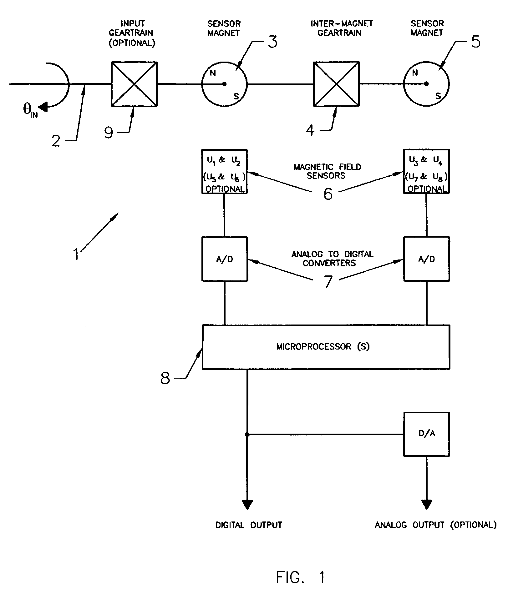
[0034]FIG. 1 is a block diagram representation of a shaft angle position sensor 1 in accordance with the present invention. The sensor includes a rotary input shaft 2 mounted for rotation through an angle designated as θIN, an input sensor magnet 3 connected for rotation responsive to rotation of the input shaft, an inter-magnet (interconnecting) gear train 4 having an input connected for rotation with the input...


PUM


Abstract

A contactless rotary shaft position sensor provides for precision computation of shaft angle for a wide range of input shaft rotational angles. The sensor includes two annular two-pole magnets which are connected by a precision, motion-transmitting gear train. An optional second gear train between one of the magnets and the input shaft can provide additional angular rotation scaling to accurately measure either fractional or a large number of multiple turns of the input shaft. The gear ratios are selected such that one of the magnets does not rotate more than one revolution. Pairs of ratiometric Hall-effect or magnetoresistive sensors provide differential voltage signals which are used for sensing angular position of each magnet over a full 360 degrees of rotation. The single-turn magnet provides an absolute, coarse indication of input shaft rotation with a typical accuracy of 2%. The gear ratio between the magnets produces several turns of the second magnet for each turn of the single-turn magnet. Since the gear ratio between the magnets is fixed, the angle sensed for the multi-turn magnet can be predicted from the position of the single-turn magnet. This is compared to the multi-turn magnet's actual sensed rotation. The result is an improvement in accuracy directly proportional to the gear ratio between the magnets. Computation of the individual magnet rotation angles and the input shaft angle is performed using a microprocessor and appropriate signal conditioning circuits. Utilizing two magnets, input shaft rotation can be accurately measured to within 0.1% of maximum range.

Description

CROSS-REFERENCES TO RELATED APPLICATIONS[0001]This application claims priority benefit to U.S. Provisional Patent Application Ser. No. 60 / 357,280, filed Feb. 14, 2002.REFERENCE TO MICROFICHE APPENDIX[0002]N / A.STATEMENT REGARDING FEDERALLY SPONSORED RESEARCH OR DEVELOPMENT[0003]N / A.BACKGROUND OF THE INVENTION 1. Field of Invention[0004]This invention relates to rotary shaft angular position sensors and, more specifically, to contactless angular sensors adapted to produce precise, linear output signals proportional to shaft position for a wide range of rotational input angles, and associated methods. 2. Description of Prior Art[0005]Shaft angular position sensing such as in rotary motion control and other applications, has been traditionally accomplished using potentiometers, synchros, or resolvers which include low reliability electrical contact arrangements such as electrical brushes and wipers. Newer technologies for angular position sensing includes optical encoders which are unre...

Claims


Application Information

Patent Timeline
IPC IPC(8): G01B7/30G01D5/04G01D5/14G01D5/16G01V3/00
CPCG01D5/142G01D5/04G01D2205/28G01D2205/26
Inventor SEGER, ERICBURANDT, WESLEYSTEUER, ANDREWFREDERICK, GARY L.
Owner BVR TECH
Why Eureka
Try Eureka