
Video data transfer method, display control circuit, and liquid crystal display device

a video data transfer and display control technology, applied in the direction of electric digital data processing, instruments, computing, etc., to achieve the effect of high operation speed

Active Publication Date: 2007-12-11
RENESAS ELECTRONICS CORP
View PDF8 Cites 11 Cited by
  • Summary
  • Abstract
  • Description
  • Claims
  • Application Information

AI Technical Summary

Benefits of technology

[0013]An objective of the present invention is to provide a video data transfer method, a display control circuit, and a liquid crystal display device that enable effective restrain of the electromagnetic interference even in the high-definition display etc. of the video data.
[0014]Further more, an objective of the present invention is to provide a video data transfer method, a display control circuit, and a liquid crystal display device adapted so that the operational speed of the data inversion process for restraining the electromagnetic interference does not become high, even though the number of the data bus for transferring the video data is reduced by partially serializing the data.
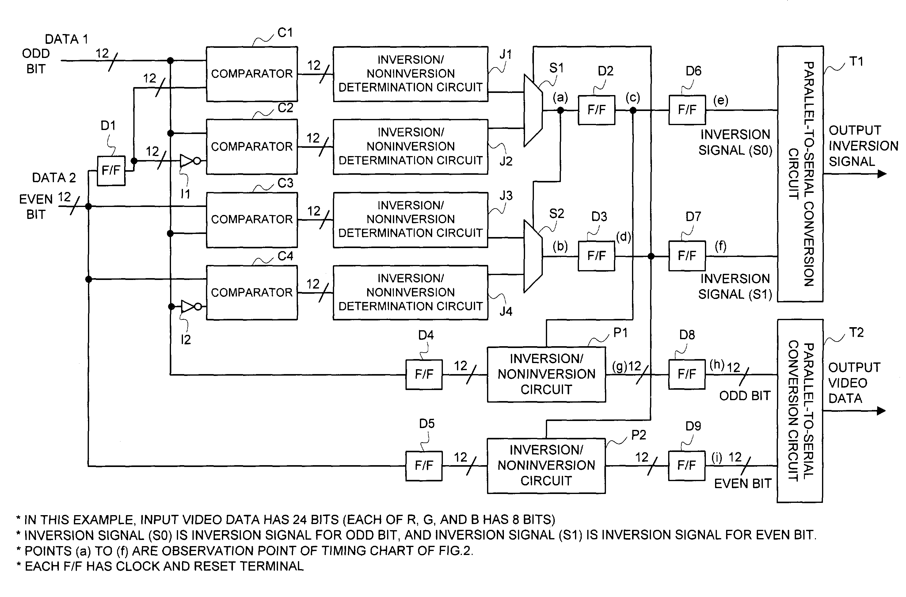
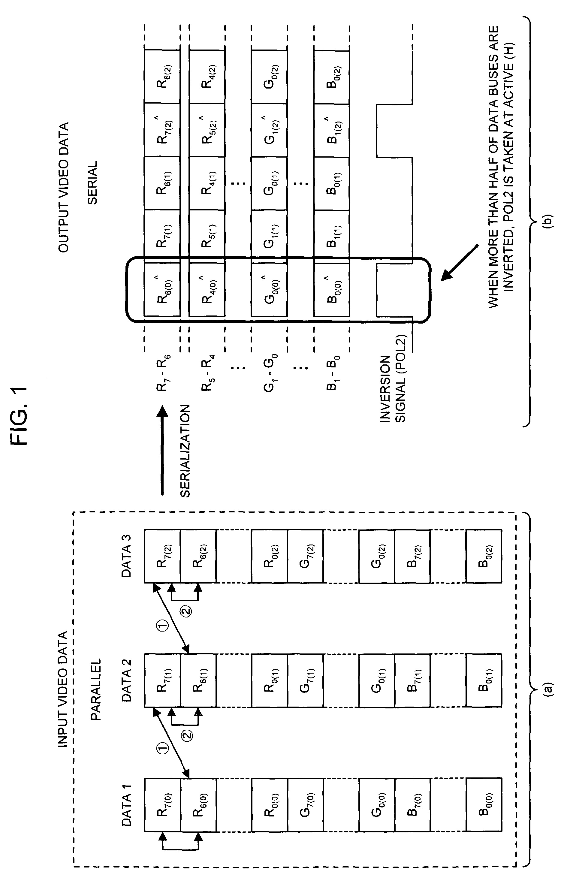
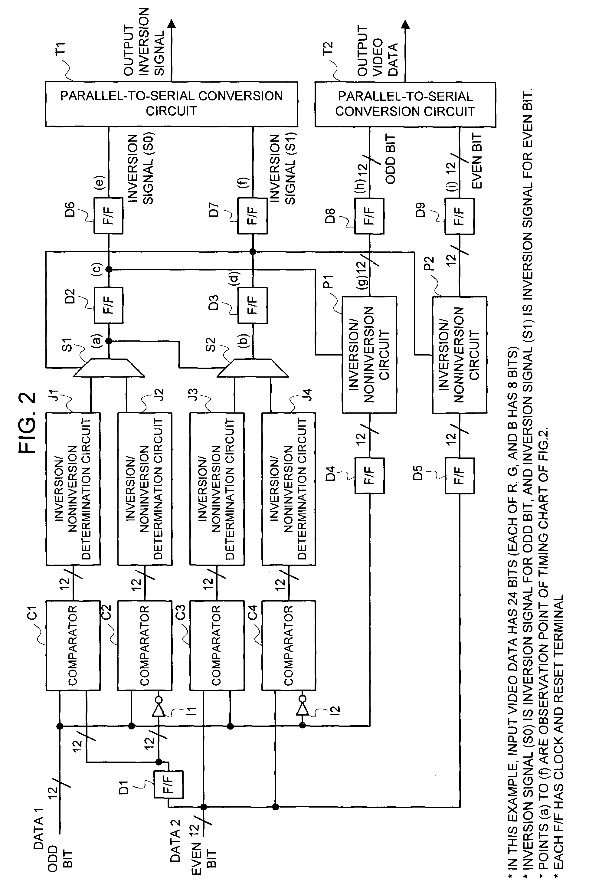
[0042]In the method of partially serializing the video data to transfer it to the signal-line diving circuit such as the source driver from the display control circuit, in a stage of the parallel data prior to making a parallel-to-serial conversion of the video data, a comparison is sequentially made of the data that corresponds to the data after serialization to take a control of the inversion / noninversion for the parallel data by whether or not the bit inversion number is more than half. As compared with the case in which a control is taken of the inversion / noninversion for the data after partial serialization of the video data, of which the operational speed became high, the operation speed of the comparator, inversion / noninversion determination circuit, etc. can be reduced.

Problems solved by technology

Also, the electromagnetic interference etc. caused by the switching for the inversion control of the logical level is also derived as a new problem.

Method used


Image

  • Video data transfer method, display control circuit, and liquid crystal display device
  • Video data transfer method, display control circuit, and liquid crystal display device
  • Video data transfer method, display control circuit, and liquid crystal display device

Examples


second embodiment

[0097]FIG. 4 is a view illustrating a signal form of the video data to be input and output in a second embodiment of the present invention. In the second embodiment, an example is shown in which the bit number of the video data to be partially serialized was taken as 4.

[0098]The input video data is the data having 3 of the parallel eight bits that correspond to each of brightness signals of red (R), green (G), and blue (B), i.e. gradation display data of 24-bit parallel data. Specifically, as shown in FIG. 4(a), the input video data is 24-bit parallel data of R0 to R7, G0 to G7, and B0 to B7, and as shown in FIG. 4(b), the output video data is 6 series of the data (for example, R7-R4, R3-R-0, G7-G4, G3-G0, B7-B4, and B3-B0) obtained by serializing (for example R7 (0), R6 (0), R5 (0), R4 (0), R7 (1), R6 (1), R5 (1), R4 (1), . . . , referred to as a “four-bit serial”) said 24-bit parallel data in four-bit unit (for example, R7 (1), R6 (1), R5 (1), and R4 (1)).

[0099]In this embodiment,...


PUM


Abstract

In a technique of partially serializing video data to transfer it from a display control circuit to a signal-line driving circuit such as a source driver, data comparisons ① and ② in the data order after serialization are made sequentially in a stage of parallel data prior to making a parallel-to-serial conversion of the video data, and determination is made as to whether or not the bit inversion number of the data is more than half to take a control of an inversion / noninversion for the transfer data. An operational speed of a comparator, an inversion / noninversion determination circuit, etc. can be reduced as compared with the case in which a control is taken of the inversion / noninversion for the data of which an operation speed became high by partially serializing the video data.

Description

BACKGROUND OF THE INVENTION[0001]The present invention relates to a control of a liquid crystal display, and more particular to a liquid crystal display device having a display control circuit for transferring video data to a liquid crystal display panel.[0002]In recent years, high definition of a display image of a computer, a television, etc. has been enhanced, and in the liquid crystal display device for treating video date thereof (image data), the data bus number and the data transfer speed have been increased year by year with an increase in the pixel number and the gradation number.[0003]FIG. 8 is a diagram illustrating a system configuration of the conventional liquid crystal display device. It is composed of an image rendering device 2A such as a personal computer (PC) and a liquid crystal display device 1A, and the liquid crystal display device 1A is configured of: a display control circuit (timing controller) 11A for inputting video data such as parallel data, synchronous...

Claims


Application Information

Patent Timeline
IPC IPC(8): G09G3/36G06F3/038G02F1/133G09G3/20G09G5/00
CPCG09G3/3611G09G5/006G09G2330/06G09G3/36
Inventor TESHIROGI, YOSHIYUKINOSE, TAKASHI
Owner RENESAS ELECTRONICS CORP
Learn More