
Image processing method

Active Publication Date: 2007-12-11
FUJIFILM HLDG CORP +1
View PDF9 Cites 13 Cited by
  • Summary
  • Abstract
  • Description
  • Claims
  • Application Information

AI Technical Summary

Benefits of technology

[0014]An object of the present invention is to solve the prior art problems described above by providing an image processing method which is utilized for a digital laboratory system and the like, which is capable of rapidly determining an image processing condition of each frame in a correct or proper manner and consequently outputting a high-quality image obtained by performing proper image processing, which requires less time between the setting of a film and the start of monitoring (verification) even if the monitoring is to be executed, and which also ensures excellent productivity and workability.

Problems solved by technology

In this method, however, a waiting time period from the setting of a film by an operator until the start of the monitoring operation is long.
Therefore, the productivity and the working efficiency are poor.
However, since the number of frames used for the setup is limited, the accuracy of image processing (correction performance) is sometimes lowered; for example, if the first several frames contain the successive scenes on the lawn, the color failure occurs, giving a magenta tone to the image.

Method used


Image

  • Image processing method
  • Image processing method
  • Image processing method

Examples


Embodiment Construction

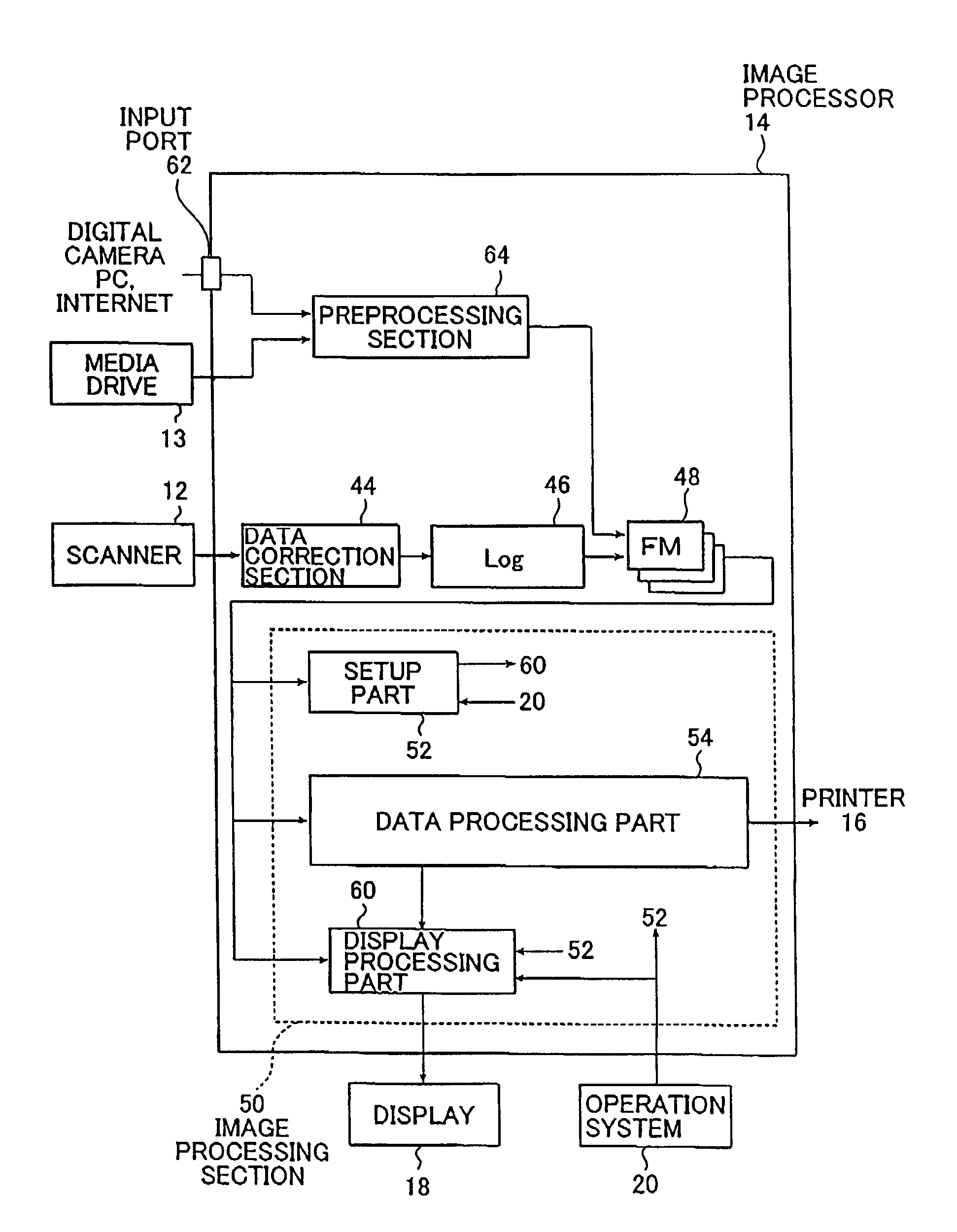
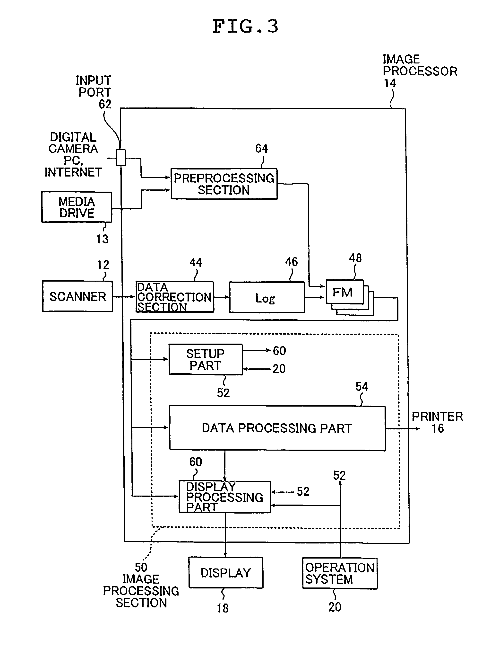
[0032]Hereinafter, an image processing method of the present invention will be described below in detail based on preferred embodiments illustrated in the accompanying drawings.

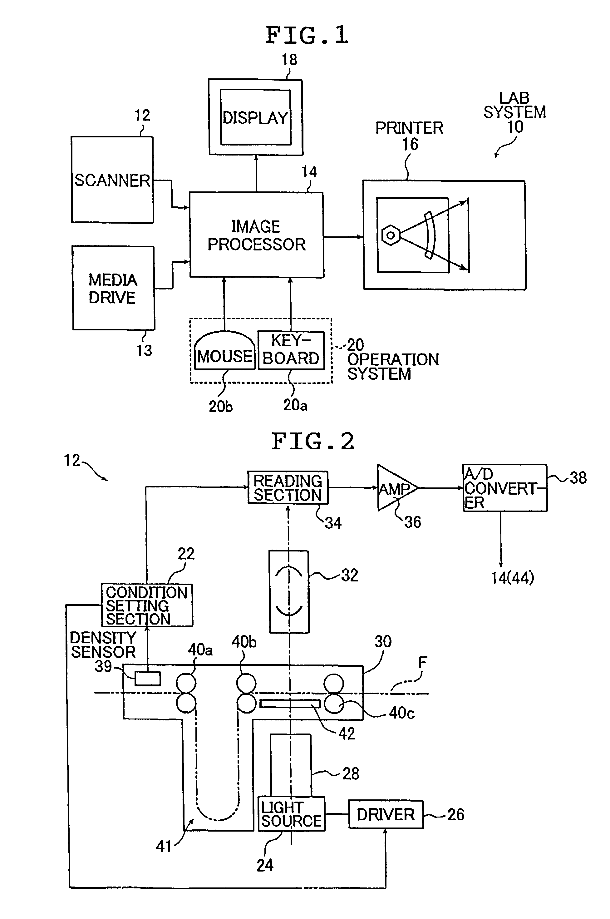
[0033]FIG. 1 is a block diagram showing an example of a digital laboratory system utilizing the image processing method of the present invention.

[0034]A digital laboratory system 10 (hereinafter, referred to simply as a lab system 10) shown in FIG. 1 photoelectrically reads an image taken on a film F or reads out an image taken with a digital camera or the like and outputs a print on which the taken image is reproduced. The lab system 10 basically comprises a scanner 12, a media drive 13, an image processor 14, a printer 16, a display 18 connected to the image processor 14, and an operation system 20 (a keyboard 20a and a mouse 20b).

[0035]On the keyboard 20a, various adjustment keys such as adjustment keys for the respective colors of C (cyan), M (magenta) and Y (yellow), a density adjustment key and a γ (gra...


PUM


Abstract

The image processing method includes successively acquiring image data of images of a plurality of frames, changing a timing with which determination of an image processing condition is started in accordance with contents of the images carried by the acquired image data, determining the image processing condition for each of the frames based on the timing using the image data of the images of the frames and performing image processing in accordance with the thus determined image processing condition to output data for output purposes. The image processing condition of each frame can be determined rapidly in a correct or proper manner in a digital laboratory system, and the workability or the productivity of print output or image file output can be improved.

Description

BACKGROUND OF THE INVENTION[0001]1. Field of the Invention[0002]The present invention relates to a technical field of an image processing method and mainly image processing utilized in a digital laboratory system, and more particularly, to an image processing method which enables rapid and correct or proper determination of an image processing condition of each frame whereby a high-quality image can be output efficiently.[0003]2. Description of the Related Art[0004]Nowadays, so-called direct exposure for projecting an image on a photographic film (hereinafter, referred to simply as a film) onto a photosensitive material (photographic paper) so as to expose the image is a main technique in printing of an image photographed on the film such as a negative film or a reversal film onto a photosensitive material.[0005]In contrast, a printer utilizing digital exposure, that is, a digital laboratory system has recently been put into practice. In the digital laboratory system, an image recor...

Claims


Application Information

Patent Timeline
IPC IPC(8): H04N1/04G03D3/00
CPCG03D3/00
Inventor YAMAMOTO, HIROYASU
Owner FUJIFILM HLDG CORP
Learn More