
Methods and circuits for realizing a performance monitor for a processor from programmable logic

Active Publication Date: 2007-12-11
XILINX INC
View PDF11 Cites 46 Cited by
  • Summary
  • Abstract
  • Description
  • Claims
  • Application Information

AI Technical Summary

Benefits of technology

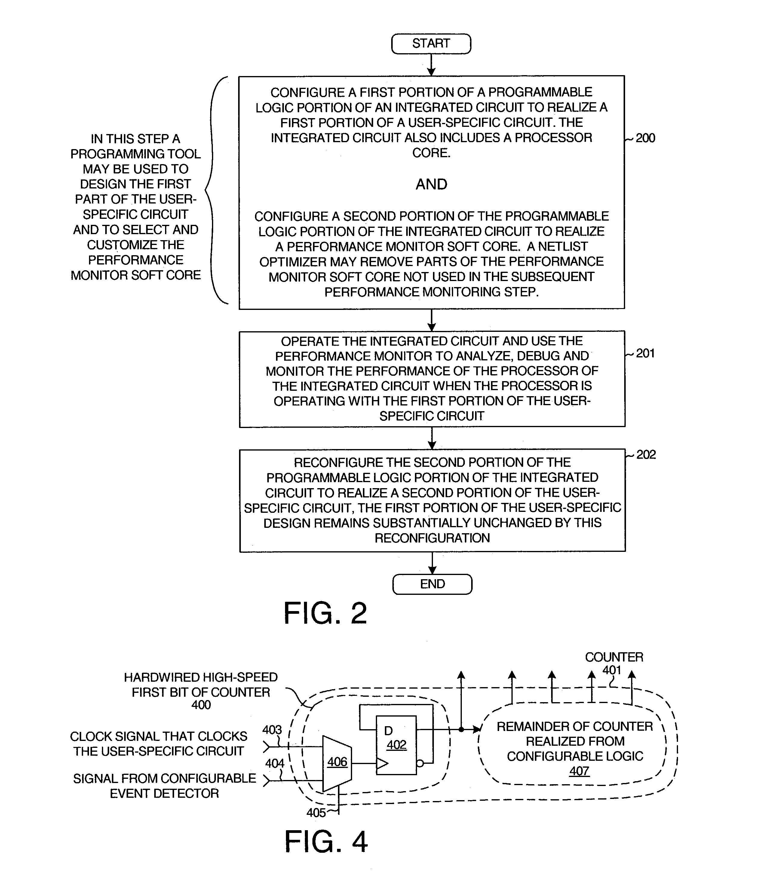
[0013]Because the portion of the integrated circuit used to realize the performance monitor is later usable in the user-specific design, the cost of having to provide a no longer desired performance monitor circuit in each integrated circuit used in the user's product is avoided. A relatively large and powerful performance monitor circuit can therefore be programmed into the integrated circuit and used to debug processor operation without significant cost because the large performance monitor circuit does not have to be embodied in the ultimate integrated circuit used by the user in the user's product.

Problems solved by technology

Although the events detected by the performance monitor of U.S. Pat. No. 6,351,724 are selectable by the user, the capabilities of the performance monitor are quite limited.
Making a larger and more flexible performance monitor having more capabilities might be nice from the perspective of the person debugging the system, but the added cost of having to provide the necessary such hardware on each microprocessor integrated circuit serves to limit the economically realizable capabilities of the performance monitor.
Despite the fact that the performance monitor is user-configurable, its configurability is limited.
The state machine is programmable, but the number of states that the state machine can have is limited by the fixed number of sequential logic elements provided for this purpose.
Added functionality in the performance monitor cannot be provided without increasing the amount of semiconductor die area dedicated to the performance monitor and without increasing the cost of the microprocessor integrated circuit.
The user of such a performance monitor is therefore sometimes stuck having to make do with a general purpose and limited function performance monitor that is not necessarily optimal for the user's diagnostic purpose.

Method used


Image

  • Methods and circuits for realizing a performance monitor for a processor from programmable logic
  • Methods and circuits for realizing a performance monitor for a processor from programmable logic
  • Methods and circuits for realizing a performance monitor for a processor from programmable logic

Examples


Embodiment Construction

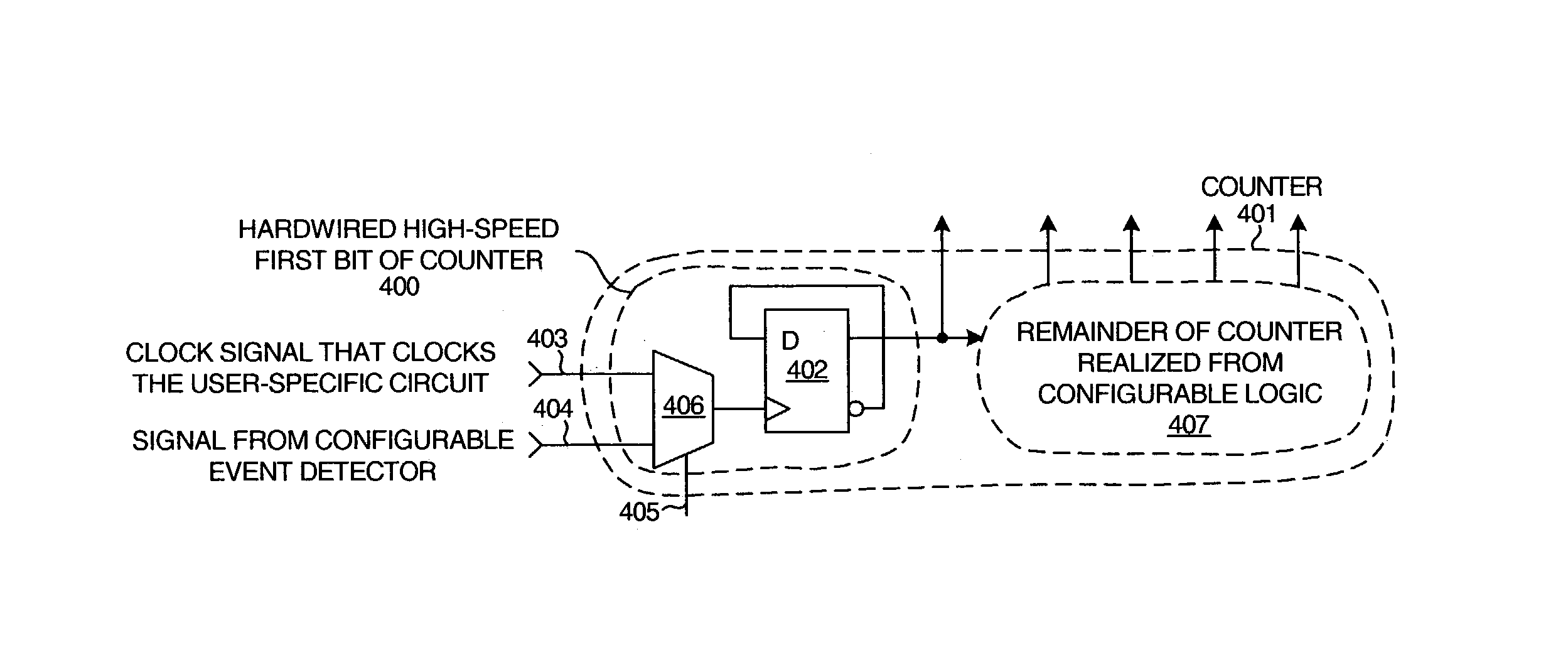
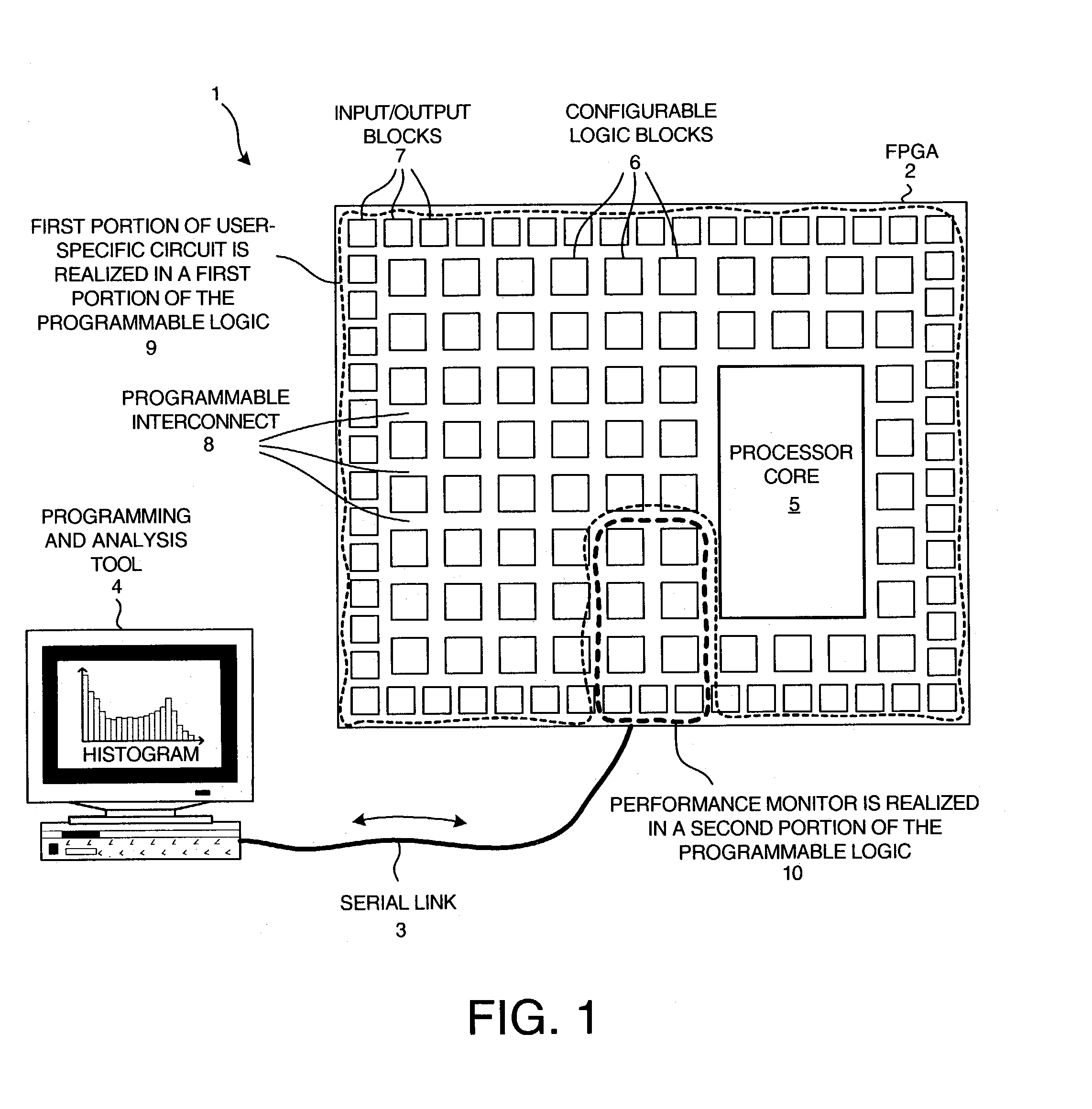
[0020]FIG. 1 is a simplified diagram of a system 1 in accordance with an embodiment of the present invention. System 1 includes an integrated circuit 2 that is linked by a serial link 3 and other interface circuitry (not shown) to a programming and analysis tool 4. The interface circuitry may, for example, include a small printed circuit board with a socket that makes electrical contact with the various terminals of integrated circuit 2. Due to space constraints and to simplify and clarify the explanation of the invention, the interface circuitry is not shown in the diagram.

[0021]In the illustrated example, integrated circuit 1 is a field programmable gate array (FPGA) that includes a processor core 5 and a programmable logic portion. The programmable logic portion includes a matrix of configurable logic blocks (CLBS) 6 surrounded by a ring of input / output blocks (IOBs) 7. The IOBs and the CLBs can be coupled; together in a desired manner by a programmable interconnect structure 8. ...


PUM


Abstract

A performance monitor is realized from programmable logic on the same integrated circuit as a processor. A user may use a programming and analysis tool to select a performance monitor soft core and to program it into the integrated circuit. The performance monitor is used to debug and / or monitor operation of the processor. After the debugging and / or performance monitoring, the portion of the programmable logic used to realize the performance monitor can be reconfigured and used to realize another portion of the user-specific circuit. Because the portion of the integrated circuit used to realize the performance monitor can be later used in the user-specific design, the cost of having to provide a no-longer-desired performance monitor in each integrated circuit used in the user's design is avoided. Because the performance monitor is realized from programmable logic, the performance monitor is more flexible than a conventional hardwired configurable performance monitor.

Description

FIELD OF THE INVENTION[0001]The present invention relates to performance monitors and programmable logic devices.BACKGROUND OF THE INVENTION[0002]In debugging and optimizing processor systems it is often desired to be able to monitor the performance of the processor. Some modern microprocessors therefore include performance monitoring hardware (also called “performance monitors”). The performance monitor circuitry is disposed on the same integrated circuit chip along with the microprocessor itself and may even be considered part of the microprocessor. A user who is debugging the system can use the performance monitor hardware on the microprocessor to collect diagnostic information about the operation of the processor. The user may, for example, set traps or halt the microprocessor at certain locations in the microprocessor code. The user can also use the performance monitor to collect state information at various points in the operation of the processor. The user can also collect hi...

Claims


Application Information

Patent Timeline
IPC IPC(8): G06F11/267G06F11/34
CPCG06F11/348G06F11/2236
Inventor JENKINS, IV, JESSE H.
Owner XILINX INC
Learn More