Integrated gyroscope and temperature sensor

a gyroscope and temperature sensor technology, applied in the field of gyroscopes, can solve the problems of large vibration environment, low inability to meet the demanding and challenging requirements of military combat systems, so as to increase the sensitivity of the device, reduce the effect of vibration environment, and minimize errors

Inactive Publication Date: 2007-12-18
ARMY US SEC THE
View PDF6 Cites 5 Cited by
  • Summary
  • Abstract
  • Description
  • Claims
  • Application Information

AI Technical Summary

Benefits of technology

[0035]Accordingly, one object of the invention is to provide a gyroscope having a temperature sensor that accurately conveys the actual temperature experienced by the gyroscope.
[0036]Another object of the invention is to provide a gyroscope that has a proof mass support structure that prevents the proof mass from touching the base substrate even when subjected to high G forces so as to prevent failure of the device.
[0037]Still another object of the present invention is to provide a SOI-MEMS gyroscope having a superior dynamic range capability.

Problems solved by technology

Although these gyroscope technologies meet most inertial requirements, they tend to be moderately expensive.
Although many organizations are developing MEMS gyroscopes for a variety of applications, most do not begin to address the demanding and challenging requirements for military combat systems.
Furthermore, actuators in the control system of the guided munition may result in a substantial vibration environment.
The criteria for achieving superior resolution while measuring large rotation rates adds difficulty to design determination since there are tradeoffs that exist in determining the mechanical structure's topology.
For example, achieving superior resolution requires substantial inertial mass available in the device.
However, when a large mass design is devised, the resulting deflections due to large values of rotational rate are generally more than the device can accommodate.
In most cases, enough electrostatic feedback force cannot be produced to counter the Coriolis forces.
Given that the MEMS gyroscope must not only survive but operate through these harsh environments, the challenge has been to develop a robust, accurate and reliable MEMS gyroscope.
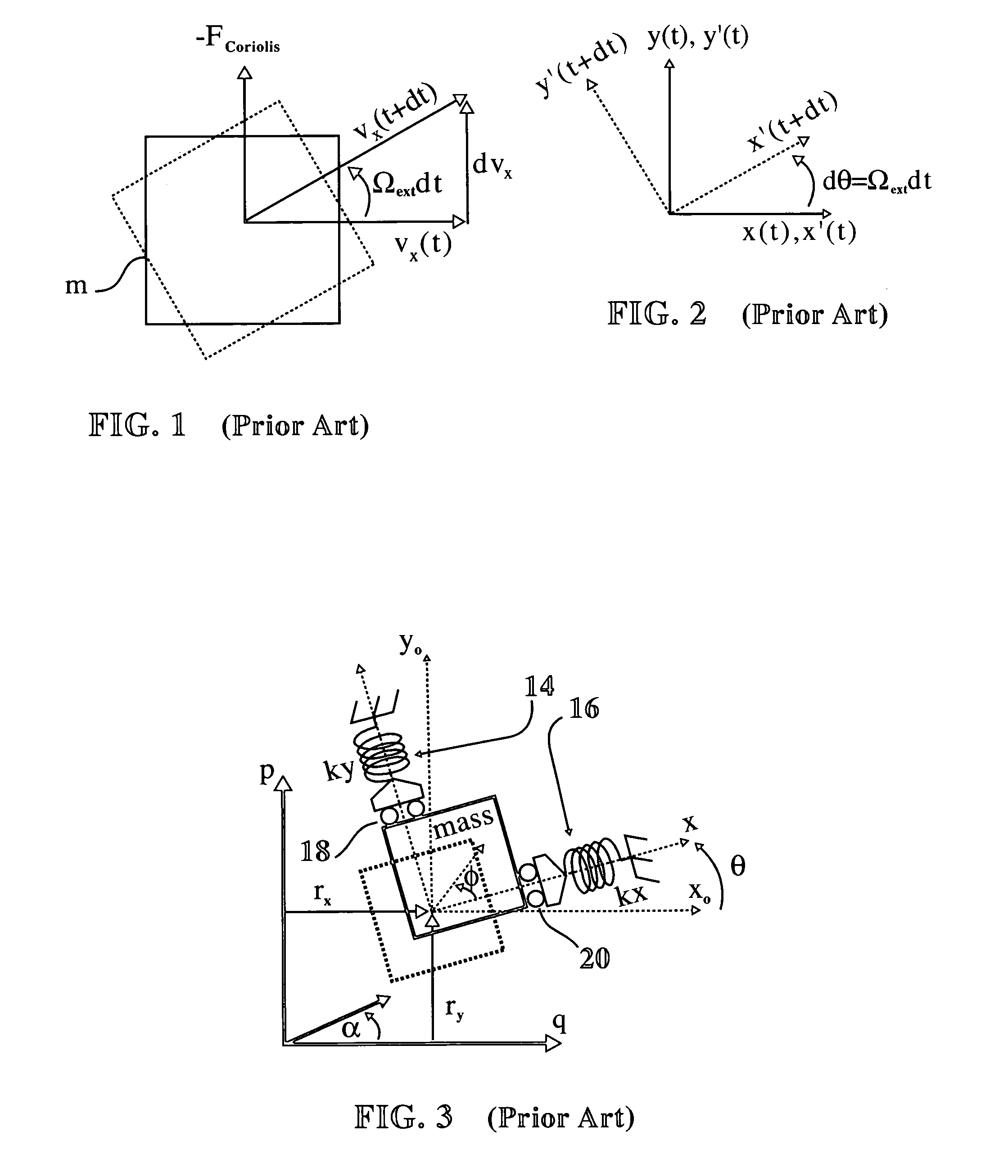
In prior art systems, the temperature sensors are prone to sense temperatures at variance from the actual temperature of the gyroscope.
Such a result causes errors in the rotational calculations.

Method used


Image

  • Integrated gyroscope and temperature sensor
  • Integrated gyroscope and temperature sensor
  • Integrated gyroscope and temperature sensor

Examples


Embodiment Construction

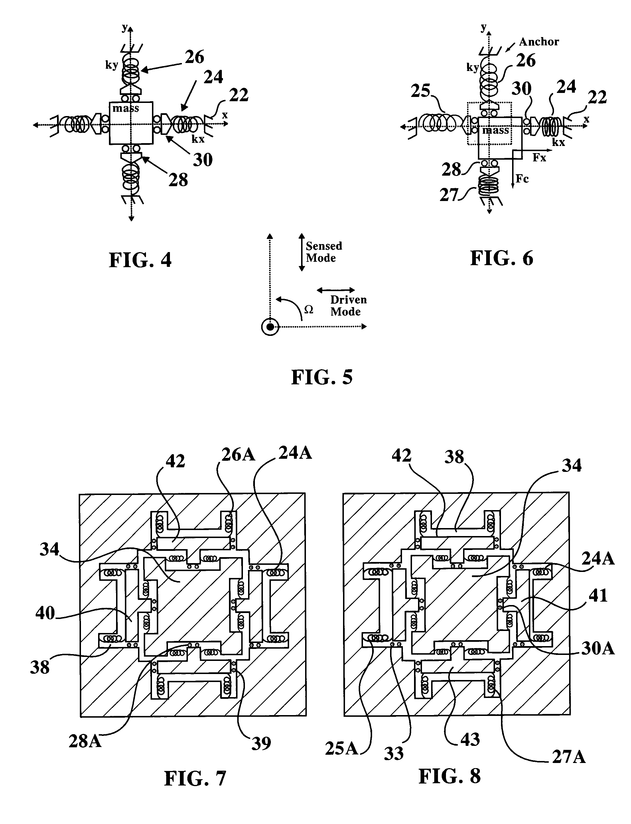
[0072]In a vibratory gyroscope, the two fundamental modes of oscillation are along the x-axis, the driven mode, and along the y-axis, the sensed mode (FIG. 5).

[0073]A conceptual suspension, shown in schematic form in FIG. 4, approximates a set of identical springs 26, 24 placed symmetrically about a central mass. The springs 26, 24 are connected to respective rolling pins 28 and 30 that allow the mass to move and slide in the y and x directions.

[0074]In FIG. 6, the actual deflection of the mass in x and y is shown. The rolling pins 28, 30 constrain the springs to act along the x-axis or the y-axis, only. In that the mass of FIG. 6 has moved to the right and downward from its position in FIG. 4, the spring 24 is compressed against anchor 22. Spring 27 is likewise compressed from the mass' movement in the y direction while springs 26 and 25 are stretched. FIGS. 4 and 6 demonstrate that the restoring forces on the mass are always orthogonal and in line with the x- and y-axes.

[0075]In a...


PUM


Abstract

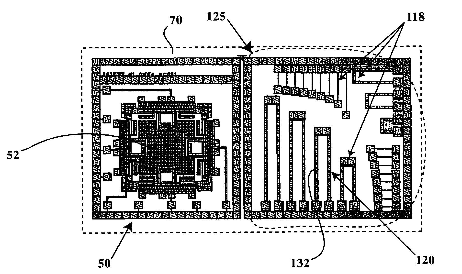
A gyroscope and temperature sensor are formed on a single chip using SOI-MEMS technology. The temperature sensor has an array of resistors to accurately detect the temperature of the gyroscope in temperatures and conditions that can range from extreme heat to extreme cold. The positioning of the gyroscope and temperature sensor on the same chip allow for extremely accurate real-time feedback of the gyroscope's temperature for utilization by a control system.

Description

[0001]The invention described herein may be manufactured, used and licensed by or for the U.S. Government for governmental purposes without payment of any royalties thereon.BACKGROUND OF THE INVENTION[0002]I. Field of the invention[0003]The present invention relates to gyroscopes.[0004]More particularly, the present invention incorporates a stationary three-fold symmetric vibratory rate gyroscope implementation and integrated temperature sensors in a thick-film silicon-on-insulator (SOI), micro electromechanical system (MEMS).[0005]II. Discussion of the Background[0006]Small, affordable, and reliable inertial components are required for small diameter precision-guided military weapon systems. Gyroscopes are inertial components or devices that can sense angular rotation and / or rotation rate. The ring laser and interferometric fiber optic gyroscopes dominate the current tactical missile system market. Although these gyroscope technologies meet most inertial requirements, they tend to ...

Claims


Application Information

Patent Timeline
Patent Type & Authority Patents(United States)
IPC IPC(8): G01C19/00
CPCG01C19/5719
Inventor HOLT, SHERRIE BURGETTKRANZ, MICHAEL S.
Owner ARMY US SEC THE
Why Eureka
Try Eureka