
Packaging system for storing and mixing separate ingredient components

a technology of ingredient components and packaging systems, which is applied in the directions of transportation and packaging, packaging goods types, liquid handling, etc., can solve the problems of system inability to inadvertently mix components during packing, mixing systems tend to add extra cost per serving, etc., and achieve better performance characteristics

Inactive Publication Date: 2007-12-18
JPRO DAIRY INT
View PDF40 Cites 65 Cited by
  • Summary
  • Abstract
  • Description
  • Claims
  • Application Information

AI Technical Summary

Benefits of technology

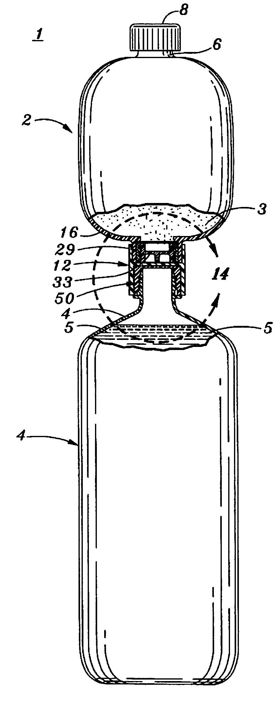
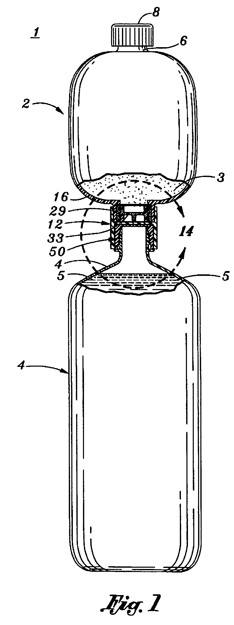
"The present invention provides a packaging system for storing and mixing two ingredient components to create a reconstitutable beverage or food product. The system includes two bottles, one for storing the first ingredient component and one for storing the second ingredient component. The first bottle has a dispensing port and a mixing port with a seal. The second bottle has a spout that can be installed into the mixing port of the first bottle. The system also includes a modified bottle cap and a threaded insert for securely attaching the two bottles together. The mixing port has a flange receiving surface or a cylindrical collar for unobstructed flow. The system further includes a threaded plug and a docking connector for interconnecting the two bottles. The technical effects of the invention include improved performance, better mixing results, and simplified use compared to previous packaging systems."

Problems solved by technology

As a result, the mixing systems tend to add extra cost per serving.
Many times such mixing systems have an increased possibility of inadvertent mixing of the components during packing or after packaging, such as during shipping, etc.
Some of the prior art systems provide a mixing flow path which only allows the first component to drain into the second component, but does not allow the second component to flow into the first bottle.

Method used


Image

  • Packaging system for storing and mixing separate ingredient components
  • Packaging system for storing and mixing separate ingredient components
  • Packaging system for storing and mixing separate ingredient components

Examples


first embodiment

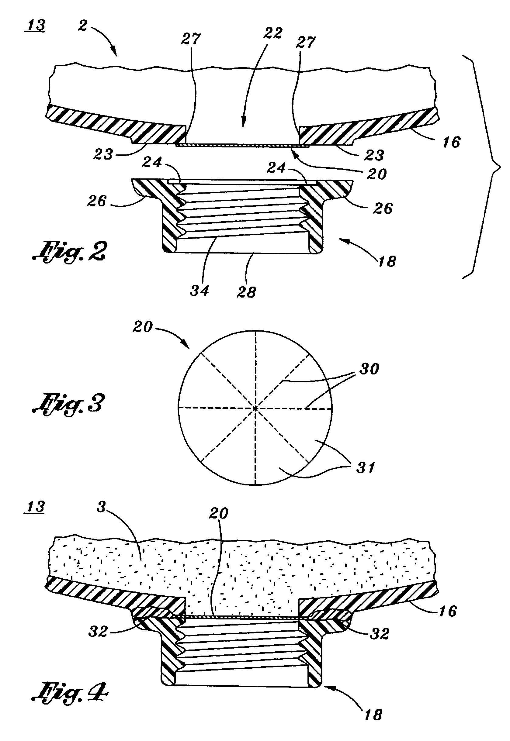
[0059]FIG. 2 depicts a cross-sectional view of the present invention which includes a mixing port 13 positioned / formed at the bottom of the first bottle 2. In particular, a mixing orifice 22 is disposed through the bottom of the first bottle 2 which is preferably circular and of which is defined by an upright cylindrical surface 27. The bottom of the first bottle 2 also includes a planar flange surface 23 which is adapted to receive a seal (see also FIG. 3) and flange 26 from a female nipple ring 18. The hermatic seal 20 is first applied to the flange surface 23 with adhesive before the female nipple 18 is permanently attached to the flange surface 23 formed on the bottom of the first bottle 2. The female nipple 18 is basically a threaded circular and cylindrical nipple which includes a flange portion 26 which is adapted to mate to the planar flange surface 23 formed on the bottom of the first bottle 2. The female nipple 18 utilizes conventional female threads 34 which are adapted t...

second embodiment

[0065]FIG. 8 depicts a cross-sectional view of a portion of the mixing port 15 which is cylindrical collar 29 formed on the bottom 16 of the first bottle 2, according to an aspect of the present invention. A mixing orifice 22 is disposed through the bottom 16 of the first bottle 2 which is preferably circular. The bottom edge of the mixing orifice 22 also includes a beveled edge or rounded edge 21 which is provided to allow the seal 20 to easily bend upwards (see FIG. 11). Furthermore, a backing shoulder 57 is formed contiguous to the beveled edge or rounded edge 21. The backing shoulder 57 and beveled edge or rounded edge 21 feature will be further discussed later in the specification.

[0066]FIG. 9 depicts a cross-sectional view of a threaded insert 33 utilized with the second embodiment of the mixing port 15, wherein the threaded insert 33 is adapted to be received into the cylindrical collar 29 from FIG. 8, according to an aspect of the present invention. The threaded insert 33 in...

third embodiment

[0072]FIG. 15 depicts a cross-sectional view of another threaded insert 43 utilized with the mixing port 45 (see FIG. 16), wherein the threaded insert 43 is adapted to be received into a shortened cylindrical collar 55 similar to collar 29 from FIG. 8, according to an aspect of the present invention. As can be seen in FIG. 15, a perforated seal 20 (see FIG. 3) is affixed to the upper end of the insert 43. In particular, the threaded insert 43 includes conventional female receiving threads 34 which are adapted to receive conventional male threads 42 disposed on the spout of the second bottle 4 which has a conventional spout 11 (see FIG. 17).

[0073]FIG. 16 depicts a cross-sectional view of the third embodiment of the mixing port 45 positioned on the bottom of the first bottle 2 which has the threaded insert 43 from FIG. 15 inserted into the shortened cylindrical collar 55, according to an aspect of the present invention. As can be seen from FIG. 16, the upper end of the insert 33 in wh...


PUM

PropertyMeasurementUnit
volumeaaaaaaaaaa
outer diameteraaaaaaaaaa
plastic fitmentaaaaaaaaaa

Abstract

A packaging system is provided for storing and mixing separate ingredient components. The system includes a first bottle used for storing a first ingredient component which includes a dispensing port disposed on a top end, a mixing port disposed on a bottom end, and a seal integrated within the mixing port. The system also includes a second bottle used for storing a second component ingredient which includes a bottle neck having an opening disposed therein wherein the neck is adapted to be installed into the mixing port of the first bottle. Also, an extended tip is formed on the distal end of the bottle neck. When the bottle neck of the second bottle is installed into the mixing port of the first bottle, the seal from the first bottle is broken by the extended tip from the second bottle establishing fluid communication between the first and second bottles and allowing the ingredient components to mix.

Description

CROSS-REFERENCE TO RELATED APPLICATIONS[0001]This application is related to co-pending U.S. patent application Ser. Nos. 11 / 451,996 and 11,451,857, both filed on Jun. 12, 2006.STATEMENT RE: FEDERALLY SPONSORED RESEARCH / DEVELOPMENT[0002]Not ApplicableBACKGROUND OF THE INVENTION[0003]1. Field of the Invention[0004]The present invention relates to a packaging system for storing and mixing separate ingredient components. In particular, the present invention relates to a packaging system which allows a first sealed bottle which contains a first component ingredient (such as powder, syrup or liquid) to be interconnected to a second bottle which contains a second component ingredient (such as liquid), such that the first and second components may be mixed together to reconstitute a beverage, consumable product, solution, mixture or the like.[0005]2. Background of the Invention[0006]There are numerous food and beverage products which are sold in powdered form and of which require water or a...

Claims


Application Information

Patent Timeline
Patent Type & Authority Patents(United States)
IPC IPC(8): B65B1/04
CPCB65D81/3211
Inventor JOHNS, GARRY P.JOHNS, COREY N.
Owner JPRO DAIRY INT
Learn More