Composite backed prestressed mirror for solar facet

a solar facet and mirror technology, applied in the field of mirror construction, can solve the problems of loss of reflectivity, relatively thicker glass and a relatively high weight, and the facets are not as robust as desired, and achieve the effect of light weight and inexpensive manufacturing

Inactive Publication Date: 2007-12-18
THE BOEING CO
View PDF30 Cites 7 Cited by
  • Summary
  • Abstract
  • Description
  • Claims
  • Application Information

AI Technical Summary

Benefits of technology

[0006]It is one object of the present invention to provide a glass structure

Problems solved by technology

This approach has several drawbacks, including losses in reflectivity as a result of the use of relatively thicker glass and a relatively higher weight.
Additionally, these mirror facets are not as robust as desired, being highly susceptible to damage during shipping, installation and use.
Furthermore, as these mirror facets have relatively weak tensile properties, their exposure to time-varying forces such as wind can cause the propagation o

Method used


Image

  • Composite backed prestressed mirror for solar facet
  • Composite backed prestressed mirror for solar facet
  • Composite backed prestressed mirror for solar facet

Examples


Embodiment Construction

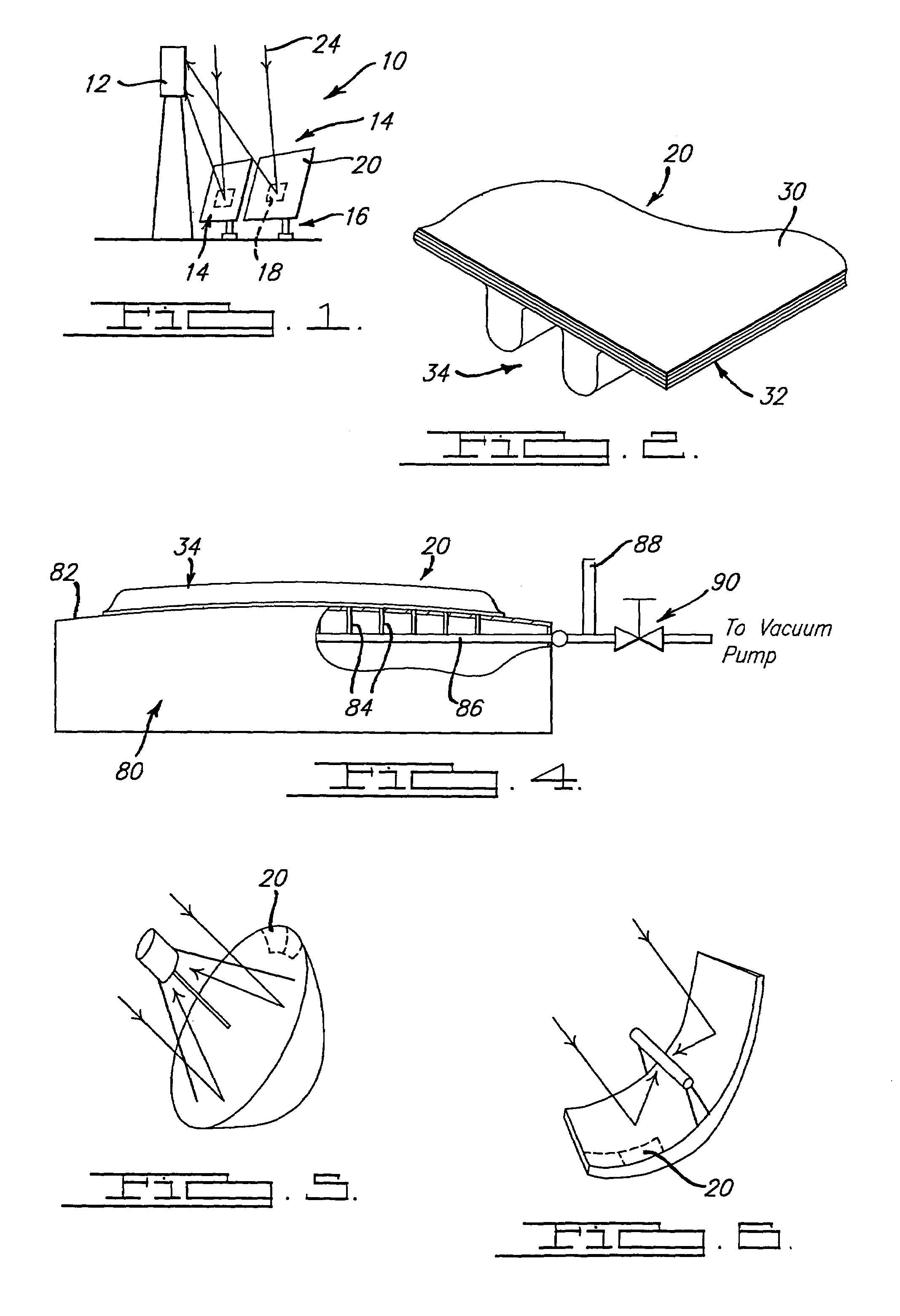
[0020]With reference to FIG. 1 of the drawings, an illustrative solar power system is generally indicated by reference numeral 10. Solar power system 10 is shown to include an elevated receiver 12 and a plurality of heliostats 14. Each of the heliostats 14 has a base structure 16 and a drive mechanism 18, as well as a glass structure 20 that is constructed according to a preferred embodiment of the present in invention. Base structure 16 and drive mechanism 18 are conventional in their construction and operation and as such, need not be discussed in detail. Briefly, base structure 16 supports drive mechanism 18 and glass structure 20. Drive mechanism 18 selectively orients glass structure 20 in a predetermined manner such that incident rays of solar energy 24 are reflected to receiver 12. Accordingly, drive mechanism 18 operates to change the position (e.g., angularity) of glass structure 20 to track the position of the sun.

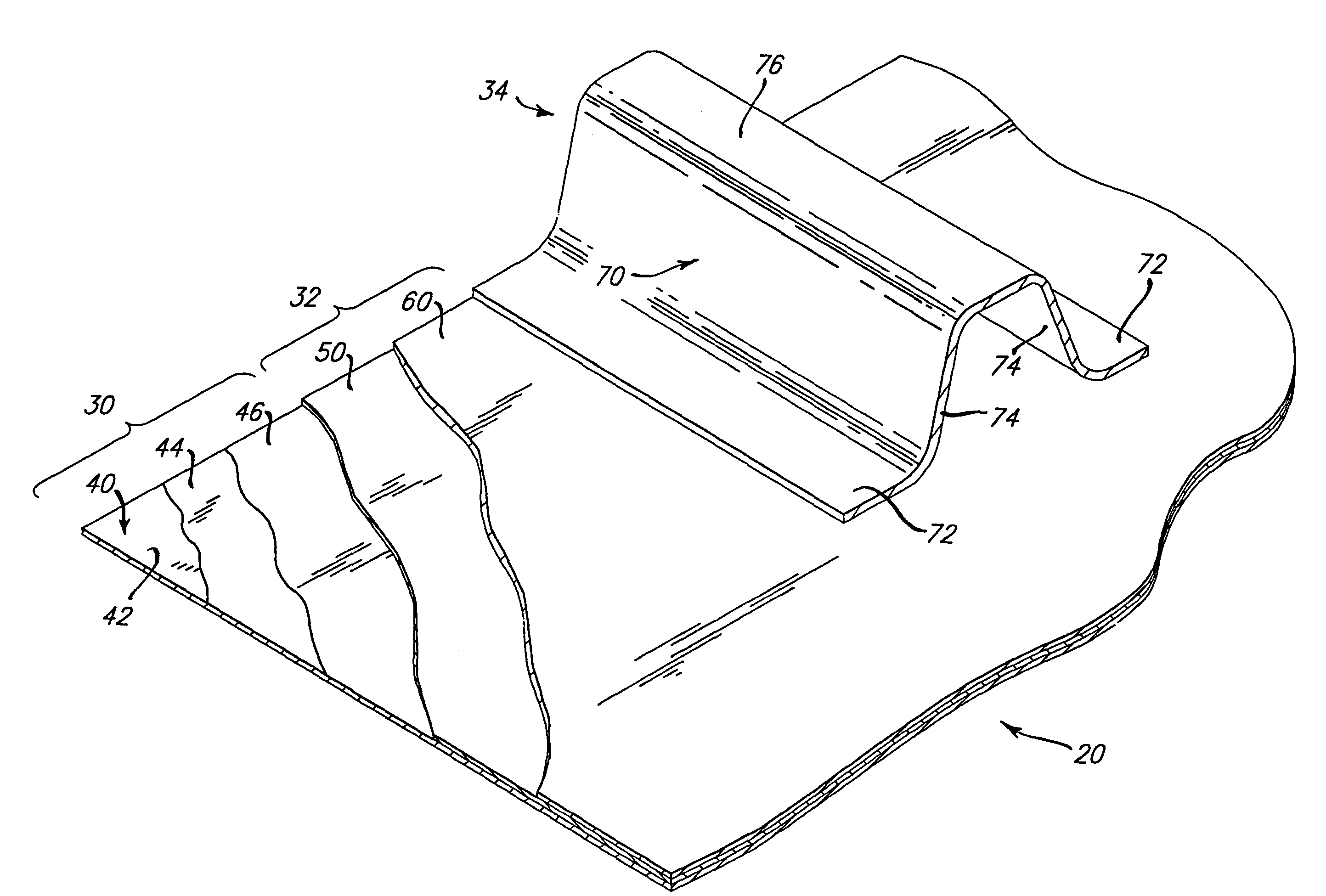
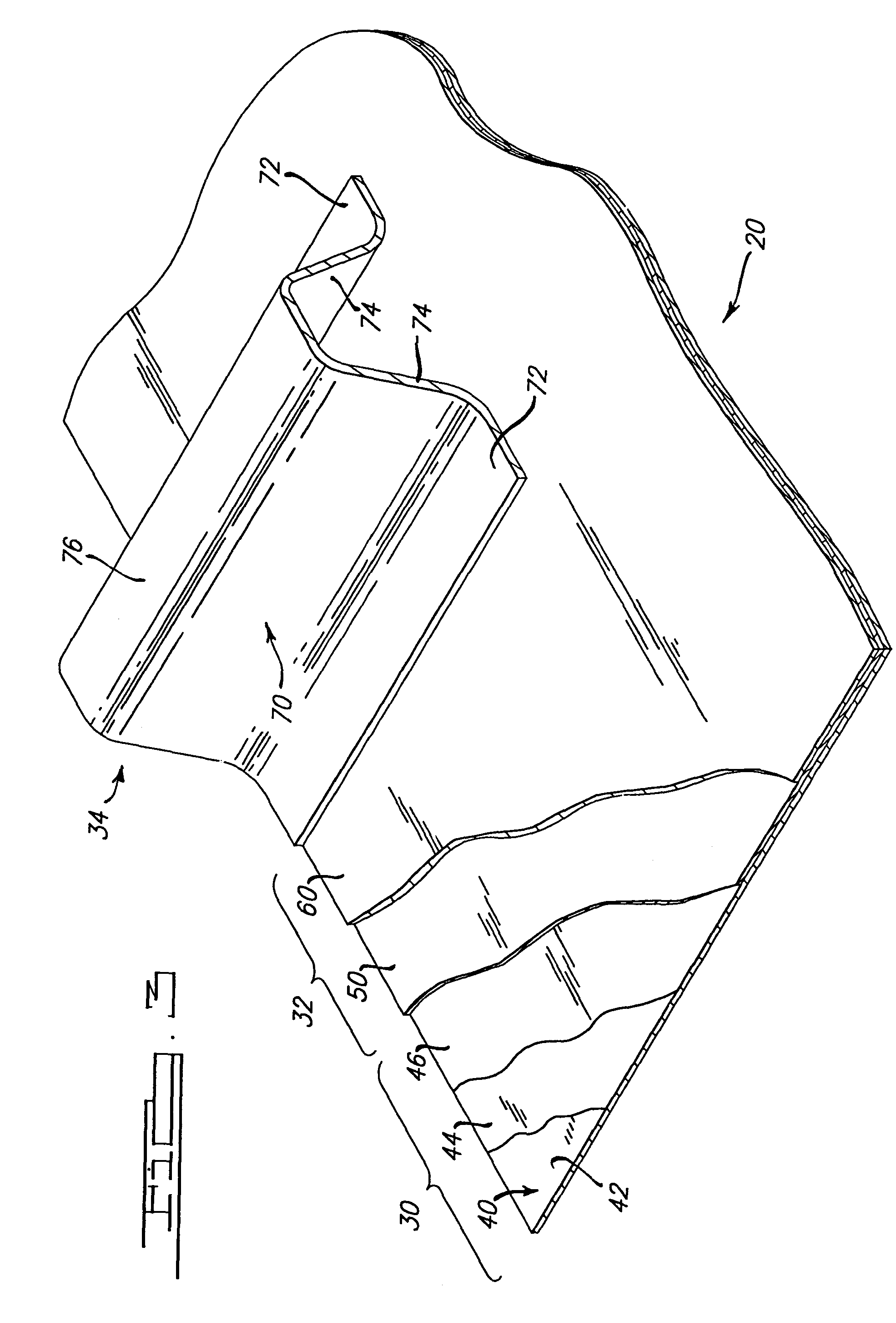
[0021]With additional reference to FIGS. 2 and 3, glass str...


PUM

PropertyMeasurementUnit
Thicknessaaaaaaaaaa
Thicknessaaaaaaaaaa
Lengthaaaaaaaaaa

Abstract

A glass structure, such as a mirror facet, having a glass member, a composite structure and a support structure. The composite structure includes a rigid interlayer which is bonded to the glass member and exerts a compressive force thereon to place the glass member in compression. The support structure is used to mount the glass structure and prevents the glass member from collapsing due to the compressive force exerted by the rigid interlayer. The glass structure is particularly well adapted for use in forming heliostats, parabolic dishes, trough concentrators, or other like elements for use in solar power systems, and does not suffer from the limitations or prior forms of such devices.

Description

TECHNICAL FIELD[0001]The present invention relates generally to the construction of mirrors and more particularly relates to a prestressed mirror and a method for fabricating the same.BACKGROUND OF THE INVENTIONBackground Art[0002]High concentration solar thermal power systems typically rely on a field of heliostats, or a parabolic dish or trough concentrators to track the sun and reflect solar radiation to a receiver where the solar energy heats a working fluid, such as steam. The working fluid is then employed to provide thermal energy for various industrial and commercial processes or to produce electricity. Similarly, concentrating photovoltaic systems use mirrors of varying types to collect solar energy where it is turned directly into electrical energy.[0003]In such systems, it is critical for performance objectives that the mirror facets which make up these systems meet stringent optical performance characteristics such as radius of curvature, reflectivity and surface slope e...

Claims


Application Information

Patent Timeline
IPC IPC(8): B32B37/14G02B5/08G02B5/10C03B23/035C03C27/12F24S23/70G02B7/182G02B7/183G02B26/08
CPCC03B23/0357F24J2/1057G02B26/0825G02B7/183Y10T156/1002Y02E10/40F24S23/82
Inventor BLACKMON, JAMES BDEAN, DAVID L
Owner THE BOEING CO
Why Eureka
Try Eureka