Multilayer hydrodynamic sheath flow structure

a technology of flow structure and hydrodynamic sheath, which is applied in the direction of transportation and packaging, laboratory glassware, instruments, etc., can solve the problems of relatively difficult fabrication and relatively complex design of conventional devices used to implement sheath flow

Active Publication Date: 2007-12-25
CYTONOMEST
View PDF10 Cites 80 Cited by
  • Summary
  • Abstract
  • Description
  • Claims
  • Application Information

AI Technical Summary

Benefits of technology

[0063]The sheath flow structure of the illustrative embodiment of the invention provides significant advantages not found in sheath flow structures of the prior art. The illustrative sheath flow structure provides three-dimensional hydrodynamic focusing using a single sheath fluid inlet. The illustrative sheath flow structure has a compact structure designed for manufacturability and requires only two structural layers in fabrication. Because the entrance to the sheath flow channels are only required on one side of the structure, the fluidic input / output structures can be simplified. Furthermore, the core flow vertical location is controllable by geometric (lithographic) resistance ratios between adjacent channels. The illustrative sheath flow structure provides accurate results that are largely insensitive to alignment between adjacent layers, as the only alignment required is to maintain the components in adjacent layers along the same centerline. The reentrant flow downstream of sample injection is then symmetric. In addition, the long path length of the branching upper sheath channels 13a, 13b results in negligible resistance ratio (therefore flow rate ratio) shift between two branch arms through misalignment of centerlines.

Problems solved by technology

Conventional devices that have been employed to implement sheath flow have relatively complex designs and are relatively difficult to fabricate.

Method used


Image

  • Multilayer hydrodynamic sheath flow structure
  • Multilayer hydrodynamic sheath flow structure
  • Multilayer hydrodynamic sheath flow structure

Examples


Embodiment Construction

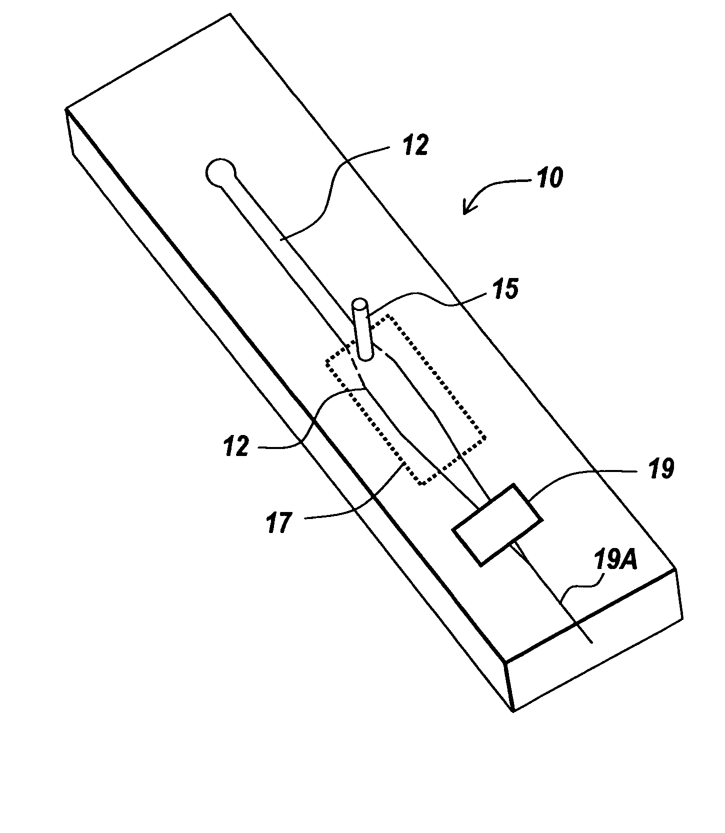
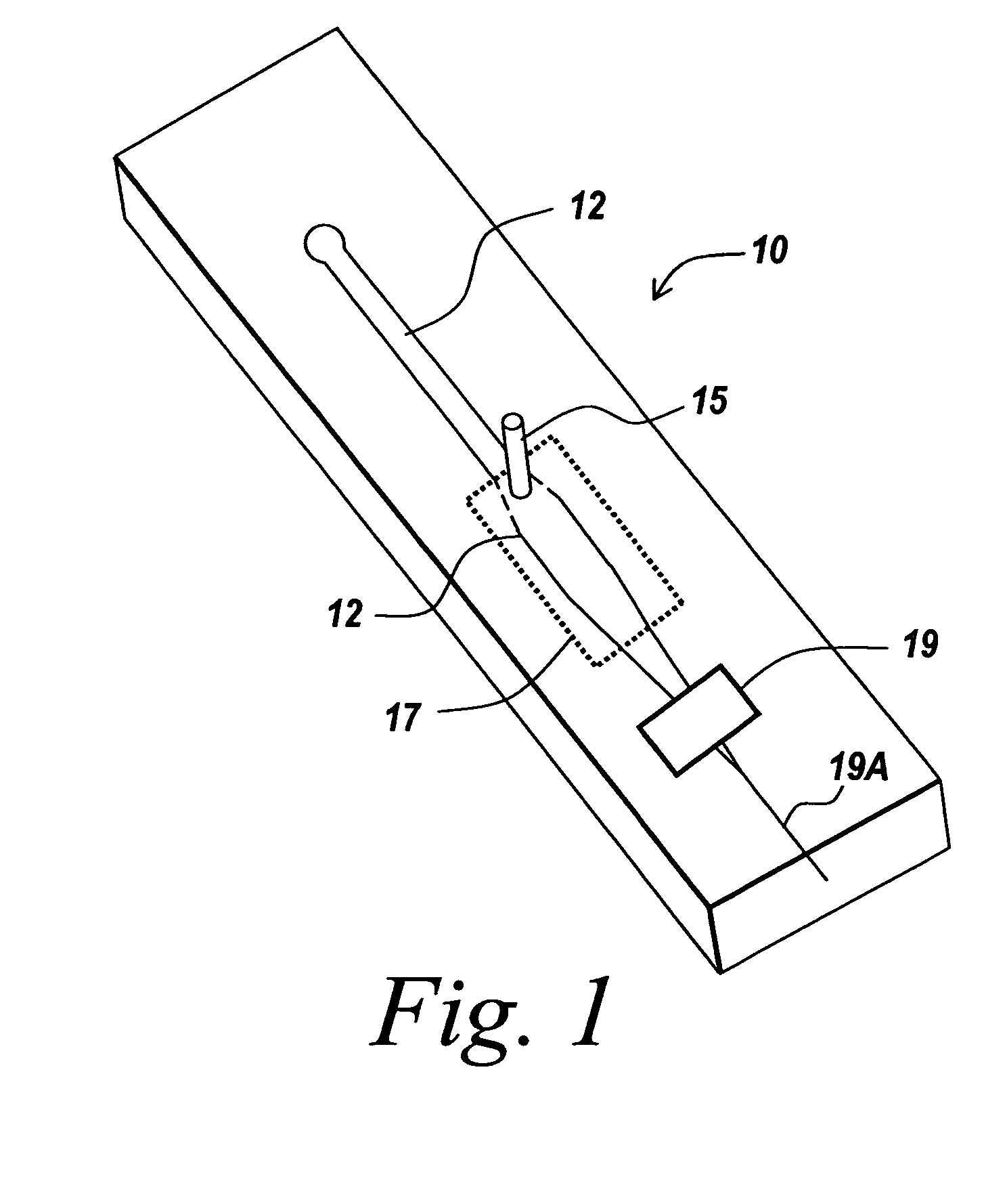
[0030]The present invention provides a system and method for producing a sheath flow in a flow channel, such as a microchannel. The present invention will be described below relative to illustrative embodiments. Those skilled in the art will appreciate that the present invention may be implemented in a number of different applications and embodiments and is not specifically limited in its application to the particular embodiments depicted herein.

[0031]As used herein, the term “microfluidic” refers to a system or device for handling, processing, ejecting and / or analyzing a fluid sample including at least one channel having microscale dimensions.

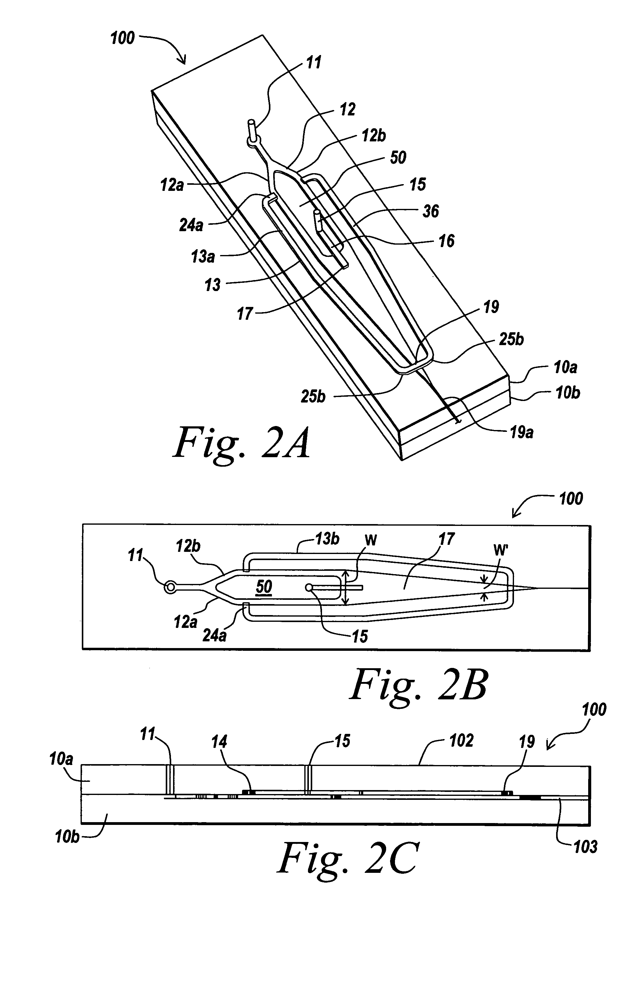
[0032]The terms “channel” and “flow channel” as used herein refers to a pathway formed in or through a medium that allows for movement of fluids, such as liquids and gases. A “microchannel” refers to a channel in the microfluidic system preferably have cross-sectional dimensions in the range between about 1.0 μm and about 500 μm, preferably be...


PUM

PropertyMeasurementUnit
sheath flow structureaaaaaaaaaa
outer diameteraaaaaaaaaa
velocitiesaaaaaaaaaa

Abstract

A microfabricated sheath flow structure for producing a sheath flow includes a primary sheath flow channel for conveying a sheath fluid, a sample inlet for injecting a sample into the sheath fluid in the primary sheath flow channel, a primary focusing region for focusing the sample within the sheath fluid and a secondary focusing region for providing additional focusing of the sample within the sheath fluid. The secondary focusing region may be formed by a flow channel intersecting the primary sheath flow channel to inject additional sheath fluid into the primary sheath flow channel from a selected direction. A sheath flow system may comprise a plurality of sheath flow structures operating in parallel on a microfluidic chip.

Description

RELATED APPLICATIONS[0001]The present invention claims priority to U.S. Provisional Application Ser. No. 60 / 516,033, filed Oct. 30, 2003, the contents of which are expressly incorporated by reference.FIELD OF THE INVENTION[0002]The present invention relates to a system and method for producing a sheath flow in a flow channel. More particularly, the present invention relates to a system and method for producing a sheath flow in a microchannel in a microfluidic device.BACKGROUND OF THE INVENTION[0003]Sheath flow is a particular type of laminar flow in which one layer of fluid, or a particle, is surrounded by another layer of fluid on more than one side. The process of confining a particle stream in a fluid is referred to as a ‘sheath flow’ configuration. For example, in sheath flow, a sheath fluid may envelop and pinch a sample fluid containing a number of particles. The flow of the sheath fluid containing particles suspended therein may be narrowed almost to the outer diameter of par...

Claims


Application Information

Patent Timeline
Patent Type & Authority Patents(United States)
IPC IPC(8): B65G51/00B01FB01F13/00B01L3/00B32B5/02G01N15/14
CPCB65G51/08B01L3/502776G01N15/1404G01N15/1484B01F13/0062B01J2219/00831B01J2219/00833B01J2219/0086B01J2219/00891B01L2200/0636B01L2300/0816B01L2300/0887B01L2400/0487B65G51/00G01N2015/1409B01J2219/00822B01F33/3011B01F25/00B07C5/00B07C5/34B01F33/3017B01L2200/0673B01L2300/0864
Inventor GILBERT, JOHN R.DESHPANDE, MANISHBUNNER, BERNARD
Owner CYTONOMEST
Why Eureka
Try Eureka