Terminal strip contacting adapter

a technology of contacting adapters and terminal strips, which is applied in the direction of coupling contact members, coupling device connections, instruments, etc., can solve the problems of increasing the possibility of errors, exposing the personnel conducting the testing to some hazards, and affecting the operation of electrical power systems

Active Publication Date: 2007-12-25
THE BOEING CO
View PDF1 Cites 7 Cited by
  • Summary
  • Abstract
  • Description
  • Claims
  • Application Information

AI Technical Summary

Benefits of technology

[0008]A plurality of safety fuses is mounted on the PCB. Each of the fuses is electrically coupled between a corresponding one of the pogo pin contactors and the second end of a corresponding one of the wires of the wire harness. The fuses augment the circuit breakers of the panel during testing, and act to shield both the automated testing apparatus and the test personnel from potentially dangerous currents that may be present on the terminal posts, and enable the use of smaller wire gauges in the adapter, and hence, a smaller adapter.
[0009]The adapter also includes a simple attachment mechanism for detachably coupling the housing to the terminal strip such that the second or outer end of each of the pogo pin contactors is held in biased contact with a corresponding one of the terminal posts.
[0011]The adapter enables the time needed to conduct a power on test of an aircraft's electrical power system to be substantially reduced, increases the reliability of the test, and provides enhanced safety for the testing equipment and personnel.

Problems solved by technology

Modern commercial, military and general aviation aircraft typically include complex electrical power systems that require extensive testing, both during manufacture and subsequent maintenance thereof.
Accordingly, this method is relatively labor intensive, and because the technician is required to probe many terminal posts and repeatedly during the course of one test sequence, the possibility of errors is increased.
Additionally, because the circuit breaker panels must be open to accomplish the voltage measurements, the previous method exposes the personnel conducting the testing to some hazards.
These problems can be even more exacerbated in larger, more complex aircraft.

Method used


Image

  • Terminal strip contacting adapter
  • Terminal strip contacting adapter
  • Terminal strip contacting adapter

Examples


Embodiment Construction

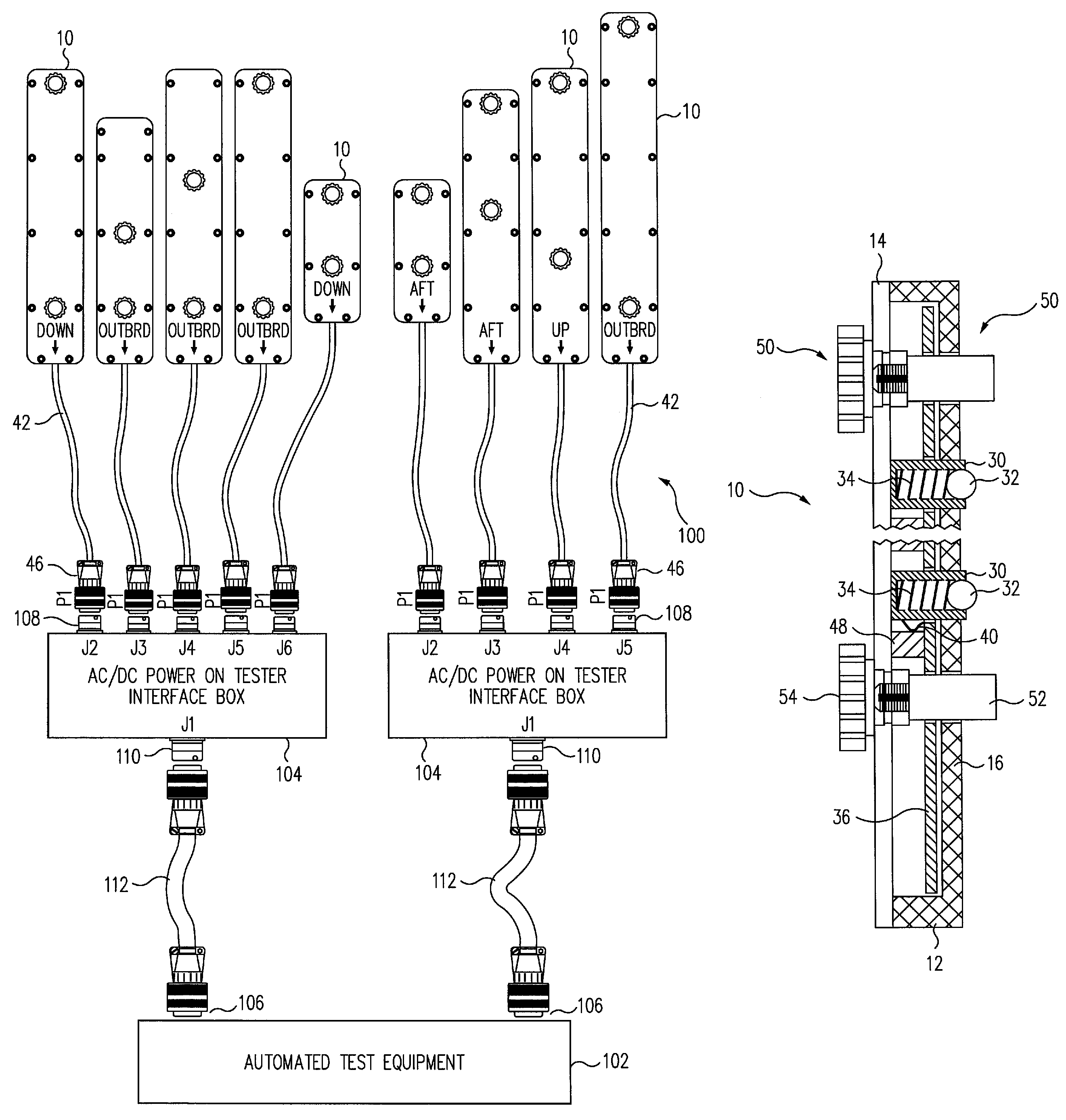
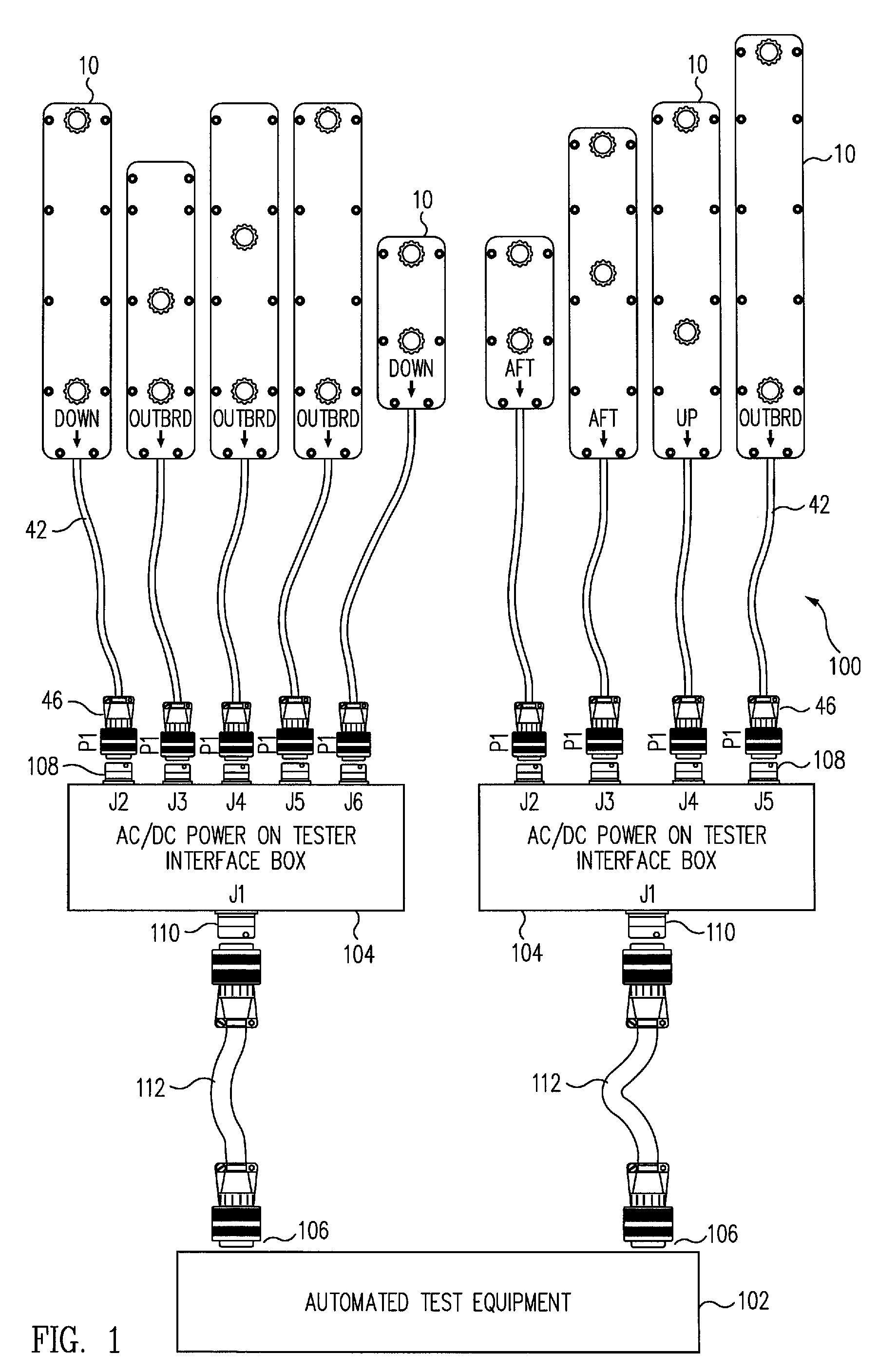
[0022]FIG. 1 is a top plan view of a system 100 for performing an automated power on test of the electrical power system of an aircraft, and which incorporates a plurality of exemplary embodiments of terminal strip contacting adapters 10 in accordance with the present invention. In addition to the terminal strip contacting adapters, the test system also comprises an automated testing apparatus 102 and a plurality of tester interface boxes 104.

[0023]As discussed above, the automated testing apparatus 102 is typically designed along with, and hence, in accordance with the circuit parameters that are specific to the particular electrical power system that it is designed to test. In the particular exemplary embodiment illustrated in FIG. 1, the testing apparatus 102 includes two input / output (I / O) connectors 106, each adapted to receive and output electrical test signals from respective ones of two circuit breaker panels (not illustrated) of the aircraft. Each panel, in turn, contains s...


PUM


Abstract

An adapter enables an automated tester to make electrical contact with a plurality of terminal posts of a terminal strip of an aircraft's electrical power system simultaneously, and includes a housing, a plurality of spring-loaded contactors protruding through a floor of the housing, and a printed circuit board disposed within the housing. Conductive leads respectively couple inner ends of the contactors to conductive traces of the printed circuit board. A wiring harness having a connector at one end is coupled to the circuit board such that each of its wires is coupled to a respective contactor via a circuit trace. Fuses are mounted on the circuit board and electrically coupled between the contactors and the harness wires. The adapter detachably couples to the terminal strip such that an outer end of each of the contactors is held in biased contact with a corresponding one of the terminal posts.

Description

BACKGROUND[0001]Modern commercial, military and general aviation aircraft typically include complex electrical power systems that require extensive testing, both during manufacture and subsequent maintenance thereof. As a consequence, automated testing equipment is typically designed and developed along with the electrical power system of the aircraft that enables, e.g., power on testing of the system to be effected in a relatively fast, safe and reliable manner.[0002]Such tests are typically conducted by equipping the automated test equipment with a test probe and then manually probing the individual terminal posts of several of the terminal strips of the aircraft's circuit breaker panels, i.e., the elongated rows of electrical terminals disposed in line with each other in the panels, to which the ends of the wires of the electrical system are coupled together with, e.g., spade lugs or other types of wire connectors.[0003]For example, in the Boeing 737 aircraft, the electrical powe...

Claims


Application Information

Patent Timeline
Patent Type & Authority Patents(United States)
IPC IPC(8): H01R13/24G01R31/50
CPCG01R31/008G01R31/024H01R13/2485H01R13/2421H01R2201/20H01R31/065G01R31/50
Inventor SCHLOTTERBECK, LYAL K.PAVLETICH, KENNETH B.
Owner THE BOEING CO
Why Eureka
Try Eureka