System and method for managing power consumption for a plurality of processors based on a supply voltage to each processor, temperature, total power consumption and individual processor power consumption

a power management and processor technology, applied in the direction of liquid/fluent solid measurement, instruments, sustainable buildings, etc., can solve the problems of not revealing a robust power management capability in the 469 patent, not managing or controlling the power delivery of the processor,

Active Publication Date: 2007-12-25
MOSAID TECH
View PDF13 Cites 49 Cited by
  • Summary
  • Abstract
  • Description
  • Claims
  • Application Information

AI Technical Summary

Benefits of technology

[0010]Sense circuits may be used to provide power information signals to the programmable control circuitry, such as voltage and current measurements of incoming power from the power delivery subsystem. An isolation barrier, such as a linear isolation amplifier or filter, may then be used to protect the programmable control circuitry from noise in the power information signals.

Problems solved by technology

Electronic systems designers are challenged by stringent and ever-changing requirements of new-generation processors.
The '469 patent does not disclose a robust power management capability.
These features may save power, but they do not manage or control the delivery of power to a processor.
While the power supply is useful in cathode sputtering systems and the like, the inability to control power output renders the power supply poorly suited for use in power management systems that require a varying power output.
The '823 patent, however, does not describe a power management system in which the brownout control may conflict with other power management objectives.
Thus, the group of power management priorities may also include a limit for power consumption at each processor, in addition to the system thermal limit, the total system power consumption limit, and the under-voltage control limit.

Method used


Image

  • System and method for managing power consumption for a plurality of processors based on a supply voltage to each processor, temperature, total power consumption and individual processor power consumption
  • System and method for managing power consumption for a plurality of processors based on a supply voltage to each processor, temperature, total power consumption and individual processor power consumption
  • System and method for managing power consumption for a plurality of processors based on a supply voltage to each processor, temperature, total power consumption and individual processor power consumption

Examples


Embodiment Construction

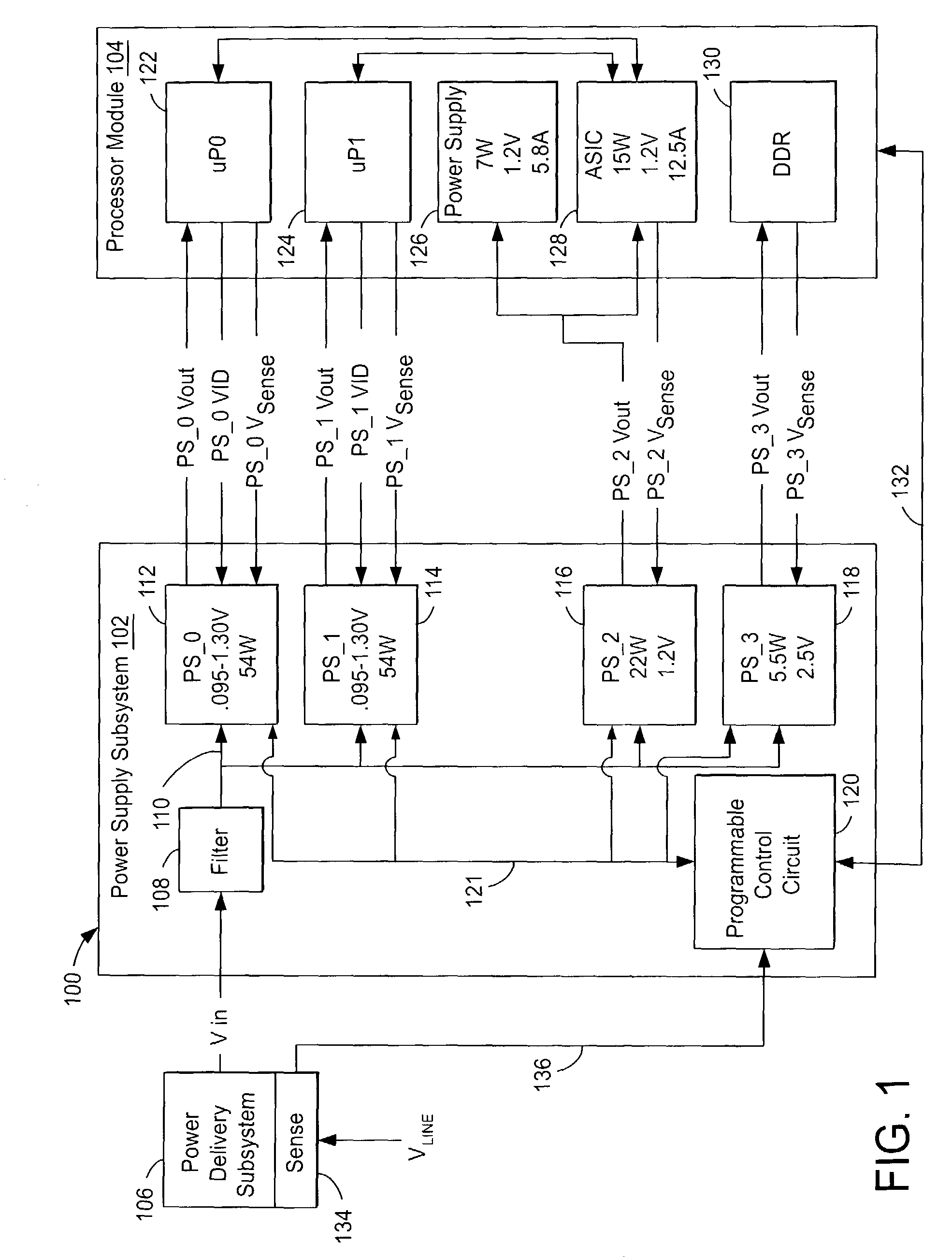
[0021]FIG. 1 is a block schematic diagram of a dual-processor electronic system 100. A programmable power supply subsystem 102 may distribute power to a multi-processor module 104; programmable power supply subsystem 102 may also include multiple power supplies 112, 114, 116, and 118. Power supply subsystem 102 and the multi-processor module 104 may be integrated on a shared board. Electronic system 100 and the associated discussion thereof are provided to illustrate principles of the invention by way of example, not by limitation.

[0022]Power supply subsystem 102 may include, for example, an isolated, high efficiency, compact DC-DC converter that provides four DC output voltages—namely, PS_O Vout, PS—1Vout, PS—2 Vout, and PS—3 Vout—from respective power supplies 112, 114, 116, and 118. The specific voltages and power outputs shown in FIG. 1 are shown by way of example to illustrate relative voltages of the respective components in system 100 in a possible commercial embodiment. Howe...


PUM


Abstract

An electronic processing system contains a power supply subsystem and a multi-processor module. Programmable control circuitry manages power consumption in the electronic system by allocating priority among a plurality of competing demands, such as total power consumption, power consumption at any one of the processors, and thermal measurements. Analog sense measurements of incoming power are transmitted to the control circuits, which are protected from noise through use of an isolation barrier established by a linear isolation amplifier.

Description

BACKGROUND OF THE INVENTION[0001]1. Field of the Invention[0002]The invention pertains to the field of power management for electronic processing systems. More specifically, power usage is controlled on the basis of sensed feedback signals, such as voltage, current and temperature.[0003]2. Discussion of the Related Art[0004]Electronic systems designers are challenged by stringent and ever-changing requirements of new-generation processors. U.S. Pat. No. 6,414,469 issued to Zhou et al. describes these challenges as being a progressive drop in operating voltage from 5V to 3.3V towards an eventual range of from 1.1V to 0.8V. At the same time, current draws are increasing from about 13A to a range between 30A and 70A per processor. The tolerance for operational voltage is shrinking, e.g., from ±5% to ±1% of design voltage, while the processors are operating at ever higher frequencies and consuming more power. All of these factors combine to require more aggressive power management featu...

Claims


Application Information

Patent Timeline
Patent Type & Authority Patents(United States)
IPC IPC(8): G06F1/00G06F11/30G06F1/26G06F1/28
CPCG06F1/26G06F1/28G06F1/3203G06F1/3296G06F1/329Y02B60/144Y02B60/1285Y02D10/00
Inventor WILLIAMS, GARY WAYNEWIRTZBERGER, PAULHARRIS, SHAUN L.
Owner MOSAID TECH
Why Eureka
Try Eureka