Liquid crystal panel, plasma display panel, and wide-screen liquid crystal television

a technology of liquid crystal television and plasma display panel, which is applied in the field of liquid crystal panel, plasma display panel, and wide-screen liquid crystal television, can solve the problems of preventing an improvement in design efficiency, no common structure of the board, and increasing design man-hours, so as to reduce assembly work and eliminate product dependence. , the effect of easy delivery in a short tim

Inactive Publication Date: 2012-12-25
FUNAI ELECTRIC CO LTD
View PDF15 Cites 3 Cited by
  • Summary
  • Abstract
  • Description
  • Claims
  • Application Information

AI Technical Summary

Benefits of technology

[0013]Since the first to fourth boards each are separate boards and therefore can be designed independently, adaptation to a different video signal system can be achieved by redesigning only the first board. The first board and the third board are disposed such that the relative position relationship therebetween is substantially the same as when disposed on the back of the plasma display panel. That is, since the plasma display panel and the liquid crystal panel can use the same boards and substantially the same relative position relationship, it is possible to reduce assembly work by unitizing the first board and the third board beforehand.
[0014]The invention thus constructed can provide the liquid crystal panel that has a board structure in common with the plasma display panel to eliminate product dependence, can be easily delivered in a short time for various destinations of different broadcast systems, and is resistant to noise. This enhances development efficiency and leads to cost reduction.
[0015]An optional aspect of the present invention provides the liquid crystal panel, wherein the fourth board and the inverter board are formed on the same board. According to the invention thus constructed, the rectifier circuit and the inverter circuit are formed on one board, which reduces assembly process and leads to cost reduction.
[0017]With this structure, the first board, the second board, the third board, and the fourth board which are also used in the liquid crystal panel are disposed on the back of the plasma display panel. Since the first to fourth boards each are separate boards and therefore can be designed independently, adaptation to a different video signal system can be achieved by redesigning only the first board. The first board and the third board are disposed such that the relative position relationship therebetween is substantially the same as when disposed on the back of the liquid crystal panel. That is, since the liquid crystal panel and the plasma display panel can use the same boards and substantially the same relative position relationship, it is possible to reduce assembly work by unitizing the first board and the third board beforehand.
[0018]The invention thus constructed can provide the plasma display panel that has a board structure in common with the liquid crystal panel to eliminate product dependence, can be easily delivered in a short time for various destinations of different broadcast systems, and is resistant to noise. This enhances development efficiency and leads to cost reduction.
[0020]Another optional aspect of the present invention provides the plasma display panel, wherein the rectifier circuit is provided with a line filter in a preceding stage. This can reduce common mode noise and differential mode noise caused by noise from a circuit connected to an AC power line, radiation noise picked up by the AC power line, noise caused by a problem with the quality of the AC power line, and the like, thus making it possible to protect a circuit connected to the rectifier circuit from noise and improve the quality of a power supply voltage outputted from the rectifier circuit.

Problems solved by technology

This is because both types of televisions adopt their respective optimum circuit components and layouts thereof However, this design method increases design man-hours, and therefore prevents an improvement in design efficiency.
Conventionally, each panel-type television has commonality of boards and components; however, there is no commonality of board structures between the liquid crystal television and the plasma television.
First, there exist circuits that are necessary to either one of the liquid crystal television and the plasma television but unnecessary to the other one, which makes the design commonality difficult.
Further, for commonality of board structures, problems with destinations and noise also exist.
While a digital processing circuit is resistant to noise, a circuit for transmitting an analog input and output signal and the like is susceptible to noise and needs to be laid out apart from an inverter circuit and a power supply circuit which are likely to be noise sources.

Method used


Image

  • Liquid crystal panel, plasma display panel, and wide-screen liquid crystal television
  • Liquid crystal panel, plasma display panel, and wide-screen liquid crystal television
  • Liquid crystal panel, plasma display panel, and wide-screen liquid crystal television

Examples


Embodiment Construction

[0033]The detailed description set forth below in connection with the appended drawings is intended as a description of presently preferred embodiments of the invention and is not intended to represent the only forms in which the present invention may be constructed and or utilized.

[0034]Hereinafter, an embodiment of the present invention will be described in the following order.

(1) Configuration of Liquid Crystal Television

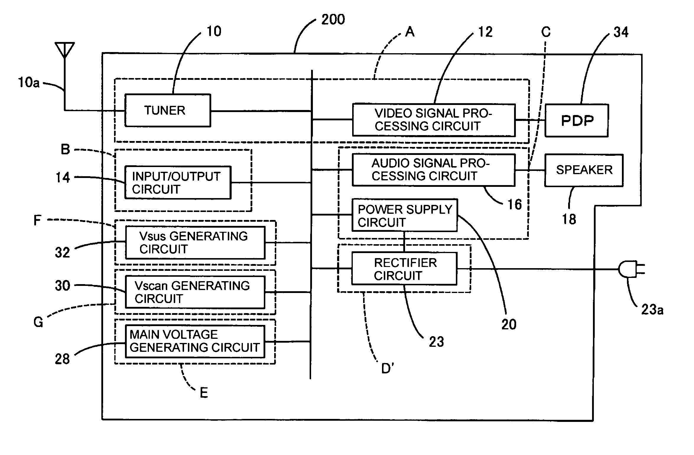
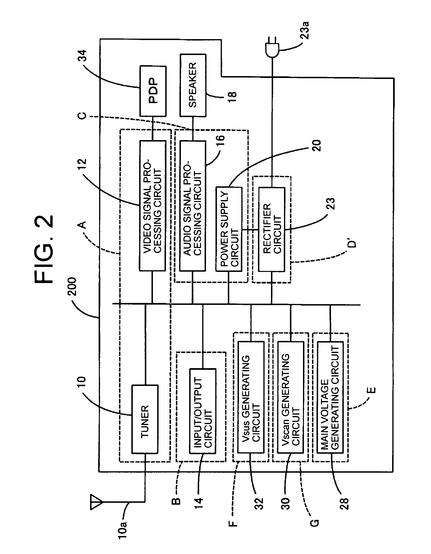
(2) Configuration of Plasma Television

(3) Board Layout of Liquid Crystal Television

(4) Board Layout of Plasma Television

(5) Summary

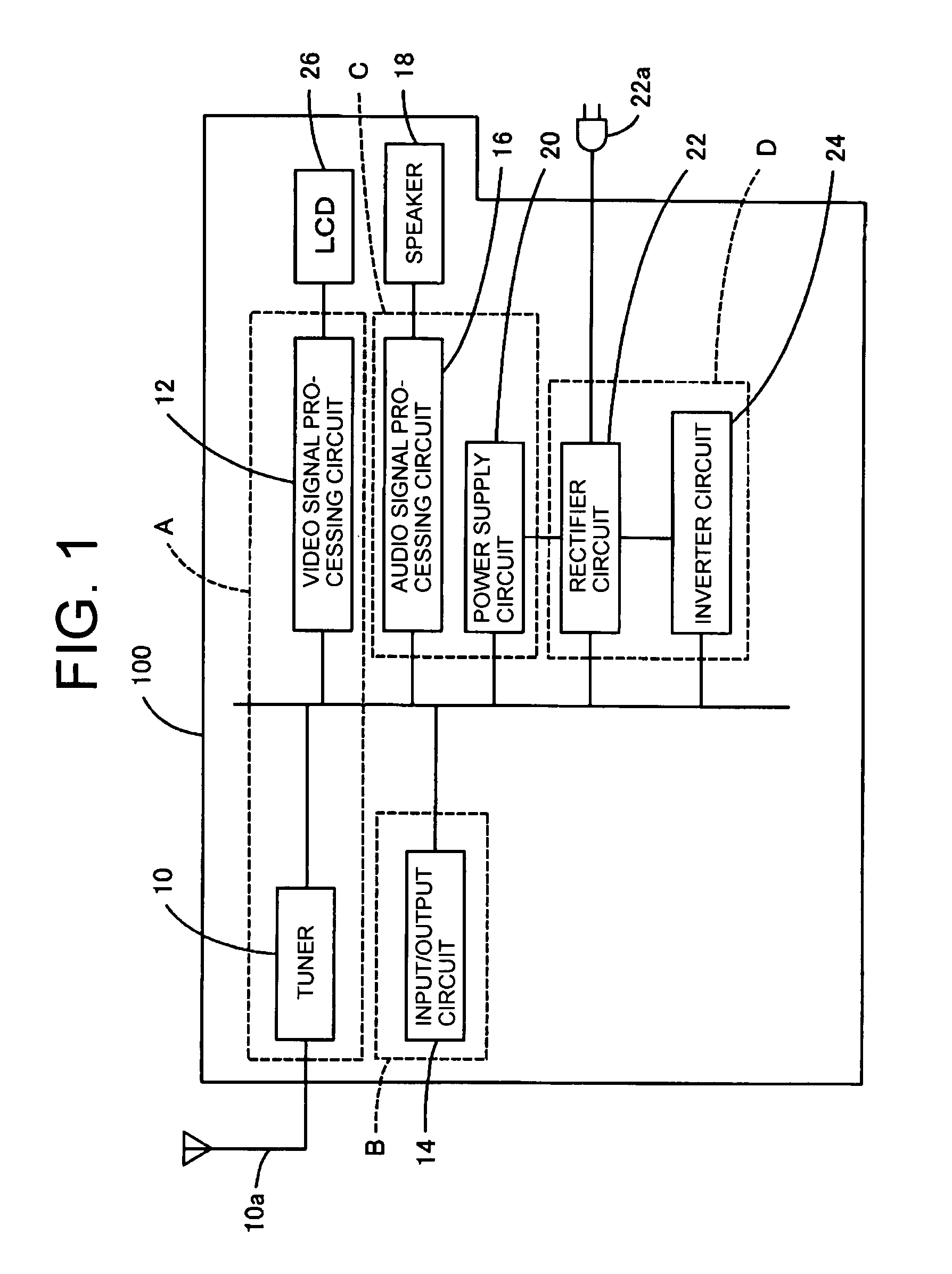
[0035](1) Configuration of Liquid Crystal Television

[0036]FIG. 1 is a block diagram showing a schematic configuration of a liquid crystal television 100 according to an embodiment of the invention. The invention is preferably applied to a wide-screen liquid crystal television with a 20-inch or larger screen to provide commonality of boards with a plasma television. In FIG. 1, the liquid crystal television 100 is configured with a tune...


PUM


Abstract

There is provided a liquid crystal television and a plasma television that can adapt to various destinations and are resistant to noise in view of the difference of circuit configurations between a liquid crystal television and a plasma television. A video signal processing circuit is formed on a digital board, an input and output circuit is formed on a jack board, an audio signal processing circuit and a power supply circuit are formed on an analog board, and a rectifier circuit and an inverter circuit are formed on an inverter board. Further, on the back of the LCD, the inverter board is disposed in a vertically oriented shape in the left, the analog board is disposed in the lower center, the digital board is disposed in the upper center adjacent to the analog board, and the jack board is disposed in the upper right.

Description

CROSS-REFERENCES TO RELATED APPLICATIONS[0001]The present application is related to the Japanese Patent Application No. 2006-252691, filed Sep. 19, 2006, the entire disclosure of which is expressly incorporated by reference herein.BACKGROUND OF THE INVENTION[0002](1) Field of the Invention[0003]The present invention relates to a liquid crystal panel, a plasma display panel, and a wide-screen liquid crystal television.[0004](2) Description of the Related Art[0005]In recent years, panel-type televisions such as liquid crystal televisions and plasma televisions have become remarkably widespread. While such a liquid crystal television and a plasma television have common functions in a video signal processing function, an audio signal processing function, a power supply circuit, and an input and output circuit, both types of televisions are manufactured based on their specific designs. This is because both types of televisions adopt their respective optimum circuit components and layouts...

Claims


Application Information

Patent Timeline
Patent Type & Authority Patents(United States)
IPC IPC(8): H04N3/14G09F9/00G09G3/20G09G3/28G09G3/296G09G3/298G09G3/36H04N5/64H04N7/173H04N21/431
CPCG09G3/3611H04N5/64H04N7/0122G09G3/3406G09G2330/06H04N5/66H04N5/70
Inventor URISU, TAKAYOSHI
Owner FUNAI ELECTRIC CO LTD
Why Eureka
Try Eureka