Pulse width modulation circuit

a pulse width and circuit technology, applied in the direction of electric variable regulation, process and machine control, instruments, etc., can solve the problems of increasing the decrease of the power supply to the motor and lighting equipment, and the decrease of the rotational speed of the motor and lighting, so as to reduce the influence of load, and slow the effect of the output voltage variation

Active Publication Date: 2008-01-01
MONTEREY RES LLC
View PDF6 Cites 23 Cited by
  • Summary
  • Abstract
  • Description
  • Claims
  • Application Information

AI Technical Summary

Benefits of technology

[0014]In this manner, the PWM circuit according to the present invention can select a plurality of voltages for output. As a result, for example, by setting a voltage outputted in a period of the additional pulse equal to a half of a voltage outputted in a period of the pulse width, it is possible to realize precise load control without causing any jitter in a PWM output waveform.
[0015]In a preferable example of the above-described embodiment, with a provision of an additional pulse detector detecting the output value of the counter and a preset period of the first additional pulse, it is possible to vary the additional pulse. For example, it is possible to set not only an additional pulse with a width corresponding to one reference clock but also an additional pulse with a width corresponding to a plurality of reference clocks such as two reference clocks. This realizes slow, smooth variation of the output voltage of the PWM circuit, which can reduce the influence to a load. Alternatively, the additional pulse register is configured to set the set value indicating the first voltage of the first additional pulse and a set value indicating a second voltage of a second additional pulse, which allows the voltage controller to control the selector so as to add the first additional pulse and the second additional pulse in sequence to the pulse width. For example, in a case where the first voltage is set to ⅔ of the output voltage of the pulse width and the second voltage is set to ⅓ thereof, the output voltage of the PWM circuit can be gradually lowered from the output voltage of the pulse width by two steps, which can realize smoother voltage variation. Further, the counter can be constituted of an up counter, a down counter, or the like, and the voltage generator can be constituted of a simple voltage divide resistance circuit. Further, adding a period of the first additional pulse or a second additional pulse to a beginning and / or an end of the pulse width enables smoother control.
[0016]For example, setting a voltage outputted in a period of the additional pulse to ½ of a voltage outputted in a period of the pulse width enables high-precision load control without causing any jitter in the PWM output waveform.

Problems solved by technology

When a high-level period of such a PWM circuit is lengthened, the electric power supplied to the motor and the lighting equipment increases, resulting in an increase in a rotational speed of the motor and brightness of the lighting.
On the contrary, when the high-level period thereof is shortened, the electric power supplied to the motor and the lighting equipment decreases, resulting in a decrease in the rotational speed of the motor and brightness of the lighting (see, for example, Japanese Unexamined Patent Application Publication No.
However, the incremental ratio cannot be 1 / 10000 or less.
But, in order to achieve that, a counter or the like with a high operational speed is needed, creating an operational limit and increasing cost.
However, since the high-level period thereof contains increased cycles and non-increased cycles both, jitter occurs in a signal waveform of the PWM output.
With the jitter in the signal waveform of the PWM output, a signal given to the load of a motor or lighting equipment will include a distortion component therein, which problematically affects the operation of the equipment.
A possible solution to remove such distortion is to use a filter or the like, but this also involves a problem of increased circuit scale and cost.

Method used


Image

  • Pulse width modulation circuit
  • Pulse width modulation circuit
  • Pulse width modulation circuit

Examples


first embodiment

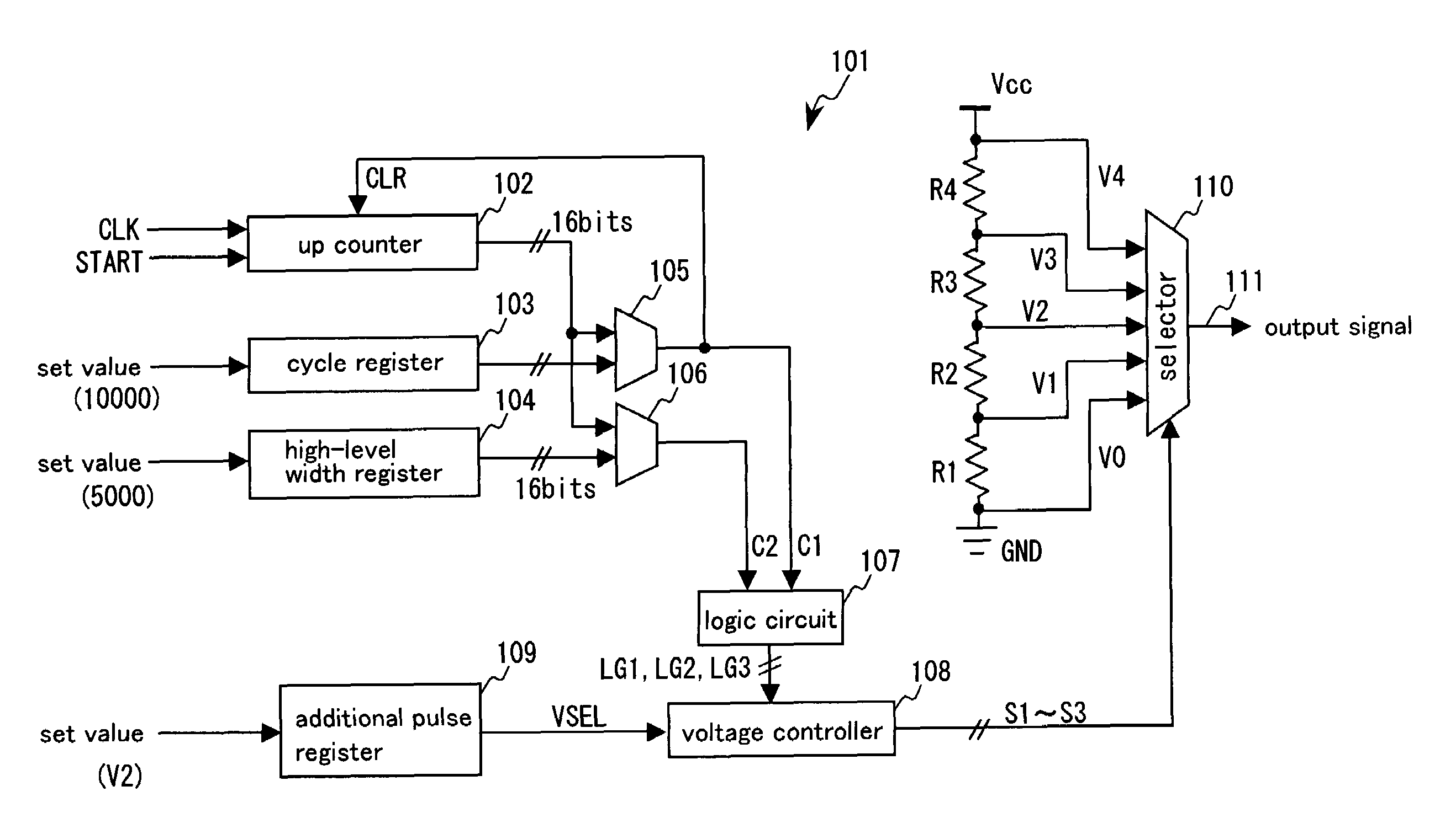
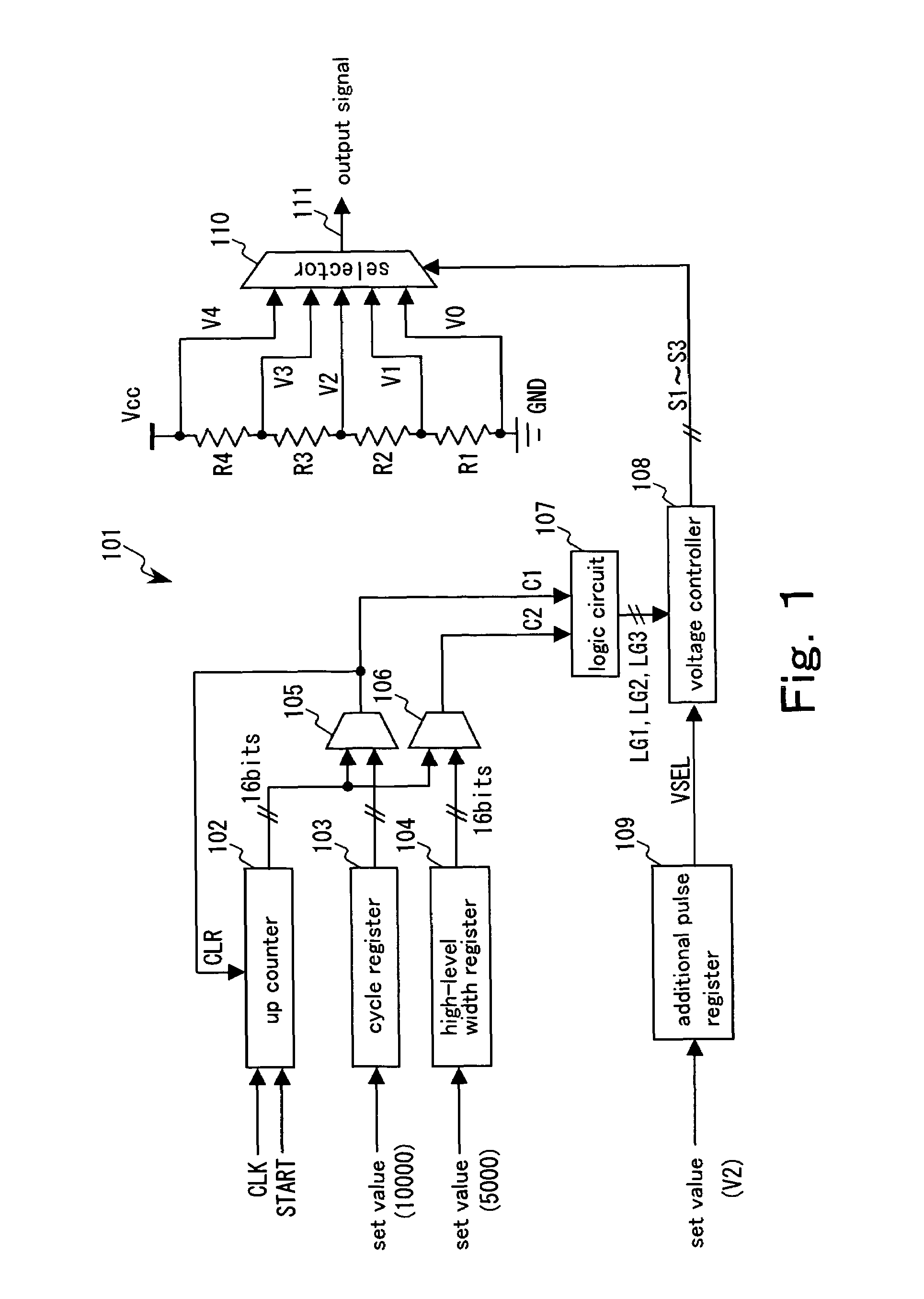
[0034]FIG. 1 is a block diagram of a PWM circuit by a multi-rate method according to a first embodiment of the present invention. A multi-rate PWM circuit 101 includes an up counter 102, a cycle value register 103, a high-level width register 104, comparators 105 and 106, a logic circuit 107, a voltage controller 108, an additional pulse register 109, a selector 110, and resistances R1, R2, R3, R4 constituting a voltage divide resistance circuit. Reference clocks CLK, a start signal START, and set values are assumed to be supplied from an exterior such as an oscillator and a CPU.

[0035]When the start signal START is inputted, the up counter 102 increments in synchronization with every reference clock CLK to output a 16-bit count value. The count value is set to 0 (zero) in an initial state of the up counter 102 and when a clear CLR signal is inputted from the comparator 105, the count value is reset to 0 (zero).

[0036]For example, the cycle value register 103 registers therein 10000 a...

second embodiment

[0053]Next, a PWM circuit by a multi-rate method according to a second embodiment of the present invention is shown in FIG. 6. The same reference symbols are used to designate the same elements as those of the first embodiment in FIG. 1. A multi-rate PWM circuit 201 is different from the first embodiment in that it additionally includes an additional pulse width register 202 and a comparator 203 and also includes a logic circuit 204 in place of the logic circuit 107.

[0054]The additional pulse width register 202, for example, registers therein 5002 as a set value in advance, and it constantly outputs the 16-bit set value (5002) to the comparator 203. The comparator 203 judges whether a 16-bit count value outputted by an up counter 102 has reached the set value (5002) registered in the additional pulse width register 202, and when the count value reaches 5002, the comparator 203 outputs a signal C3 with a width corresponding to one reference clock to the logic circuit 204.

[0055]Simila...

third embodiment

[0061]Next, a PWM circuit by a multi-rate method according to a third embodiment of the present invention is shown in FIG. 8. The same reference symbols are used to designate the same elements as those in FIG. 1 and FIG. 6. A multi-rate PWM circuit 301 is different from the second embodiment in a logic circuit 302, a voltage controller 303, and an additional pulse register 304.

[0062]In the logic circuit 302, though the same signals C1 to C3 as those in the second embodiment are inputted thereto, signals generated thereby are four signals LG1, GL2, LG3, LG4. Further, the operation of outputting the signals LG1 and LG2 is the same as that in FIG. 7. As the signal LG3, the same signal as the signal C2 is outputted. The signal LG4 is generated to have a width from a falling edge of the signal C2 with a width t2 to a rising edge of the signal C3 with a width t21. A circuit generating the signal LG4 can be realized by using the SRFF 152 and the inverter 153 described in FIG. 4.

[0063]The a...


PUM


Abstract

A PWM circuit includes a counter, a cycle register, a cycle detector, a pulse width register, a pulse width detector, an additional pulse width register, a voltage generator, a selector, and a voltage controller. The voltage controller controls the selector so as to add a first additional pulse at a first voltage to the end of a pulse width, based on a cycle detection signal outputted by the cycle detector, a pulse width detection signal outputted by the pulse width detector, and a set value indicating the first voltage of the first additional pulse outputted by the additional pulse register, thereby deciding a voltage outputted from the PWM circuit and a period in which the voltage is output.

Description

CROSS REFERENCE TO RELATED APPLICATION[0001]This application is based upon and claims the benefit of priority from Japanese Patent Application No. 2006-086372, filed on Mar. 27, 2006, the entire contents of which are incorporated herein by reference.BACKGROUND OF THE INVENTION[0002]1. Field of the Invention[0003]The present invention relates to a PWM circuit according to a multi-rate method.[0004]2. Description of the Related Art[0005]Conventionally, a PWM circuit that controls electric power supplied to a load by varying a duty ratio of a pulse signal has been in use for controlling speed of a motor, dimming of lighting equipment, and the like. When a high-level period of such a PWM circuit is lengthened, the electric power supplied to the motor and the lighting equipment increases, resulting in an increase in a rotational speed of the motor and brightness of the lighting. On the contrary, when the high-level period thereof is shortened, the electric power supplied to the motor and...

Claims


Application Information

Patent Timeline
Patent Type & Authority Patents(United States)
IPC IPC(8): G05F1/40
CPCH03K7/08
Inventor MATSUI, SATOSHI
Owner MONTEREY RES LLC
Why Eureka
Try Eureka