Apparatus and method for multi-phase transformers

a multi-phase transformer and apparatus technology, applied in the direction of circuit-breaking switches, process and machine control, instruments, etc., can solve the problems of increasing the footprint of dc-dc converters, ics are less tolerant of power supply inaccuracy, and inaccurate power supplies

Active Publication Date: 2008-01-01
INTEL CORP
View PDF44 Cites 47 Cited by
  • Summary
  • Abstract
  • Description
  • Claims
  • Application Information

AI Technical Summary

Problems solved by technology

A power supply ideally delivers the nominal voltage levels with assurance and precision, but power supplies are typically inaccurate due to a number of factors.
However, some ICs are less tolerant to power supply inaccuracies, and some ICs may require a nominal operating voltage other than the standard TTL and CMOS voltages.
If too much power is dissipated while the DC-DC converter is operating, heat sinks will be needed and the footprint of the DC-DC converter will be increased.
This is especially undesirable when the amount of available board space is limited.
Furthermore, maximum current consumption, current density and current transient demands of high performance microprocessors have been increasing by 50% per generation in spite of supply voltage (VCC) scaling.
Reduction of VCC makes the problem of delivering larger currents with high conversion efficiency even more challenging, especially since the maximum acceptable VCC variation is on the order of 10% of the target VCC value.
Employing traditional methods to meet VCC variation targets on the microprocessor die in the presence of large current transients requires a prohibitively large amount of on-die decoupling capacitance (decap).

Method used


Image

  • Apparatus and method for multi-phase transformers
  • Apparatus and method for multi-phase transformers
  • Apparatus and method for multi-phase transformers

Examples


Embodiment Construction

[0016]Reduction of supply voltage (VCC) for low voltage applications (e.g., mobile / handheld devices) makes the problem of delivering larger currents with high conversion efficiency quite challenging. Employing traditional methods to meet VCC variation targets on the micro-processor die in the presence of large current transients requires a prohibitively large amount of on die decoupling capacitance especially for low voltage platforms. An alternative technique for meeting VCC variation is the use of a motherboard voltage regulator and converter module (VRM) that operates at a high frequency. Furthermore, expensive solutions are required to minimize impedance (Zext) of the off chip supply network carrying high current from the VRM to the die across the board, sockets and package traces.

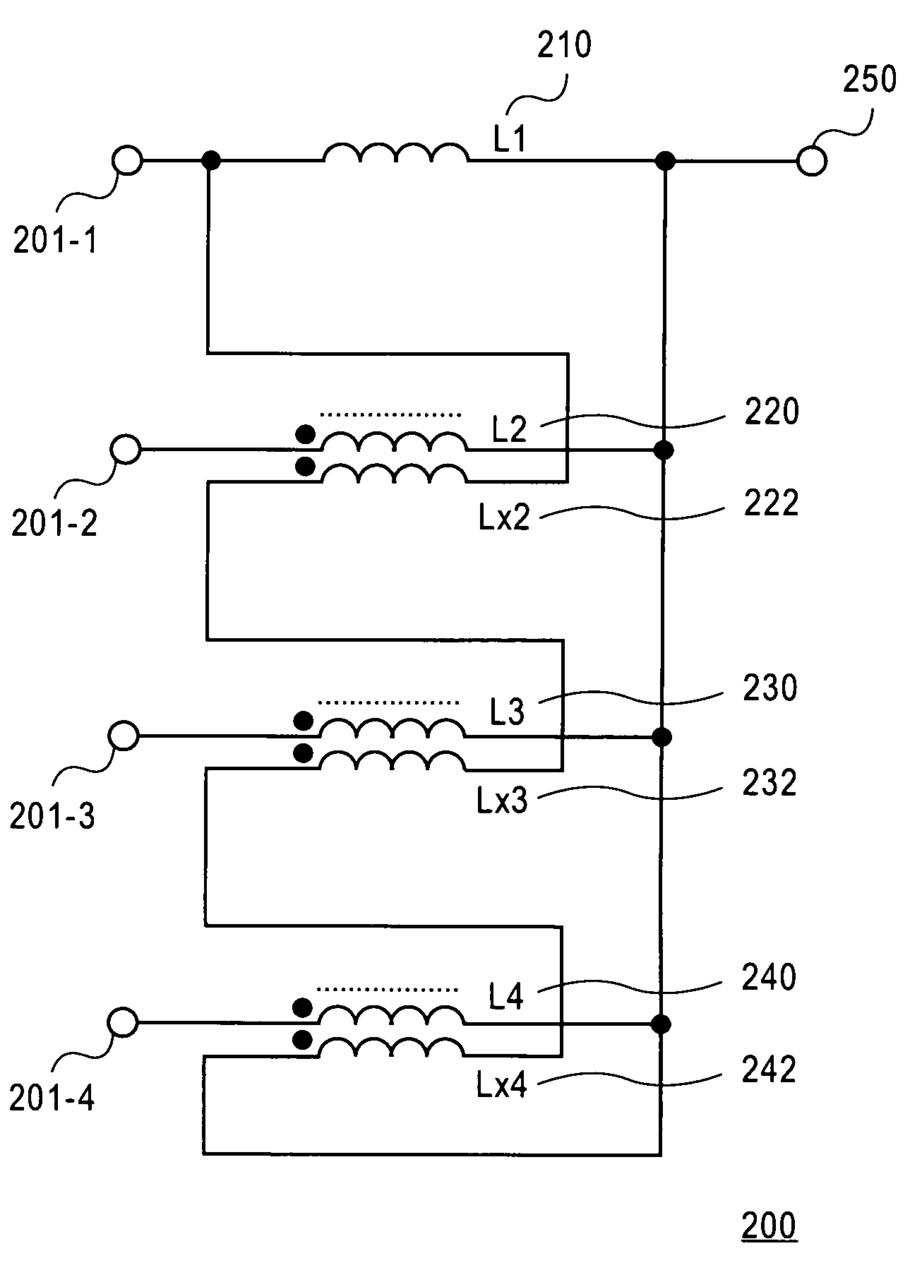
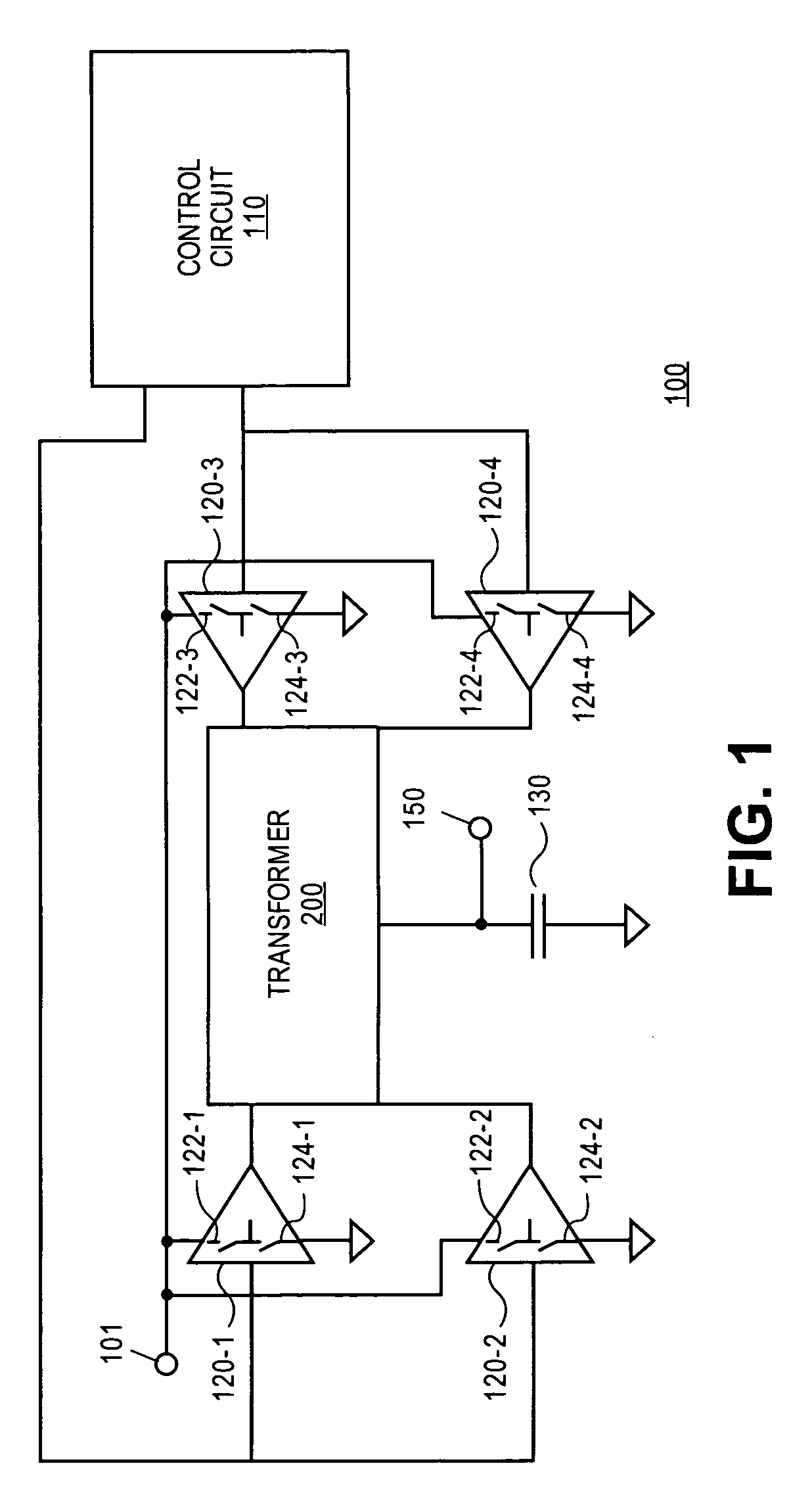
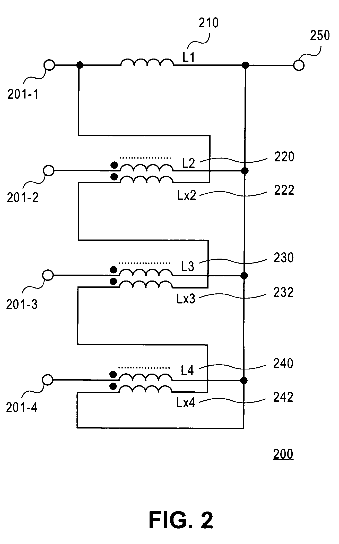
[0017]Accordingly, FIG. 1 illustrates a direct current (DC) to DC (DC-DC) converter 100, which my be either packaged or integrated on a die of a processor in accordance with one embodiment. A DC-DC con...


PUM


Abstract

A method and apparatus for multi-phase transformers are described. In one embodiment, a coupled inductor topology for the multi-phase transformers comprising N primary inductors. In one embodiment, each primary inductor is coupled to one of N input nodes and a common output node. The transformer further includes N−1 secondary inductors coupled in series between one input node and the common output node. In one embodiment, the N−1 secondary inductors are arranged to couple energy from N−1 of the primary inductors to provide a common node voltage as an average of N input node voltages, wherein N is an integer greater than two. Other embodiments are described and claimed.

Description

FIELD OF THE INVENTION[0001]One or more embodiments of the invention relate generally to the field of integrated circuit and computer system design. More particularly, one or more of the embodiments of the invention relate to a method and apparatus for multi-phase transformers.BACKGROUND OF THE INVENTION[0002]The power supplies in a computer system are designed to meet the specific power requirements of the integrated circuit chips (ICs) that are the components of the system. The nominal operating voltages for the ICs are typically known because most ICs are manufactured to meet industry standards for device operation. For example, the nominal supply voltage for transistor-transistor logic (TTL) devices is 5.0 volts while the nominal supply voltage for complementary metal oxide semiconductor (CMOS) devices is 3.3 volts.[0003]A power supply ideally delivers the nominal voltage levels with assurance and precision, but power supplies are typically inaccurate due to a number of factors....

Claims


Application Information

Patent Timeline
Patent Type & Authority Patents(United States)
IPC IPC(8): H02M5/00
CPCH02M3/1584H01F37/00H01F27/38H01F27/42H01F2038/026
Inventor SCHROM, GERHARDHAZUCHA, PETERGARDNER, DONALD S.DE, VIVEK K.KARNIK, TANAY
Owner INTEL CORP
Why Eureka
Try Eureka