Air-powered electro-mechanical fuze for submunition grenades

a technology of electro-mechanical fuzes and submunitions, which is applied in the direction of ammunition fuzes, weapons, weapon components, etc., can solve the problems of unreliable ribbon deployment to unscrew the firing pin, unreliable required striking action of the firing pin, and the carrier's forward velocity of the grenade moving at the speed of the carrier, so as to improve the safety and reliability of the fuze

Inactive Publication Date: 2008-01-08
UNITED STATES OF AMERICA THE AS REPRESENTED BY THE SEC OF THE ARMY
View PDF10 Cites 27 Cited by
  • Summary
  • Abstract
  • Description
  • Claims
  • Application Information

AI Technical Summary

Benefits of technology

[0013]It is an object of the invention to provide a DPICM fuze that improves fuze safety and reliability by deriving a

Problems solved by technology

When expelled from its carrier round (such as a missile or projectile), the grenade is moving at the carrier's forward velocity and may tumble in the airstream.
As is typical of this type of DPICM fuze, however, the required striking action by the firing pin is not very reliable because its mechanical sensitivity depends on the angle of impact.
Additionally, the ribbon that is deployed to unscrew the firing pin is unreliable.
For slow spinning or nonspinning rounds, such as those carried by rockets, the ribbon does not generate enough spin on its own to reliably unscrew and release the firing pin.
Current DPICM fuzes generally have low primary reliability (function on target), as low as 96% or less, which means that the population of grenades deployed by the weapon automatically loses, in the aggregate, up to 4% of its effectiveness on first impact with the target.
One of the primary causes of this unreliability is the poor off-axis sensitivity of the current stab-detonator mechanisms.
However, the addition of a time-delay self-destruct (SD) mechanism, whether pyrotechnic or electronic in function, introduces new hazards.
For example, a DPICM-loaded Multiple Launch Rocket System (MLRS) rocket battery or an MLRS-bearing mobile platform may suffer damage leading to unintended grenade dispense.
This damage can occur due to a rocket-propelled grenade (RPG) attack or the impact of an improvised explosive device (IED) or an incident in a munitions depot.
An even greater hazard results from accidental dispense of the described self-destruct type grenades due to

Method used


Image

  • Air-powered electro-mechanical fuze for submunition grenades
  • Air-powered electro-mechanical fuze for submunition grenades
  • Air-powered electro-mechanical fuze for submunition grenades

Examples


Embodiment Construction

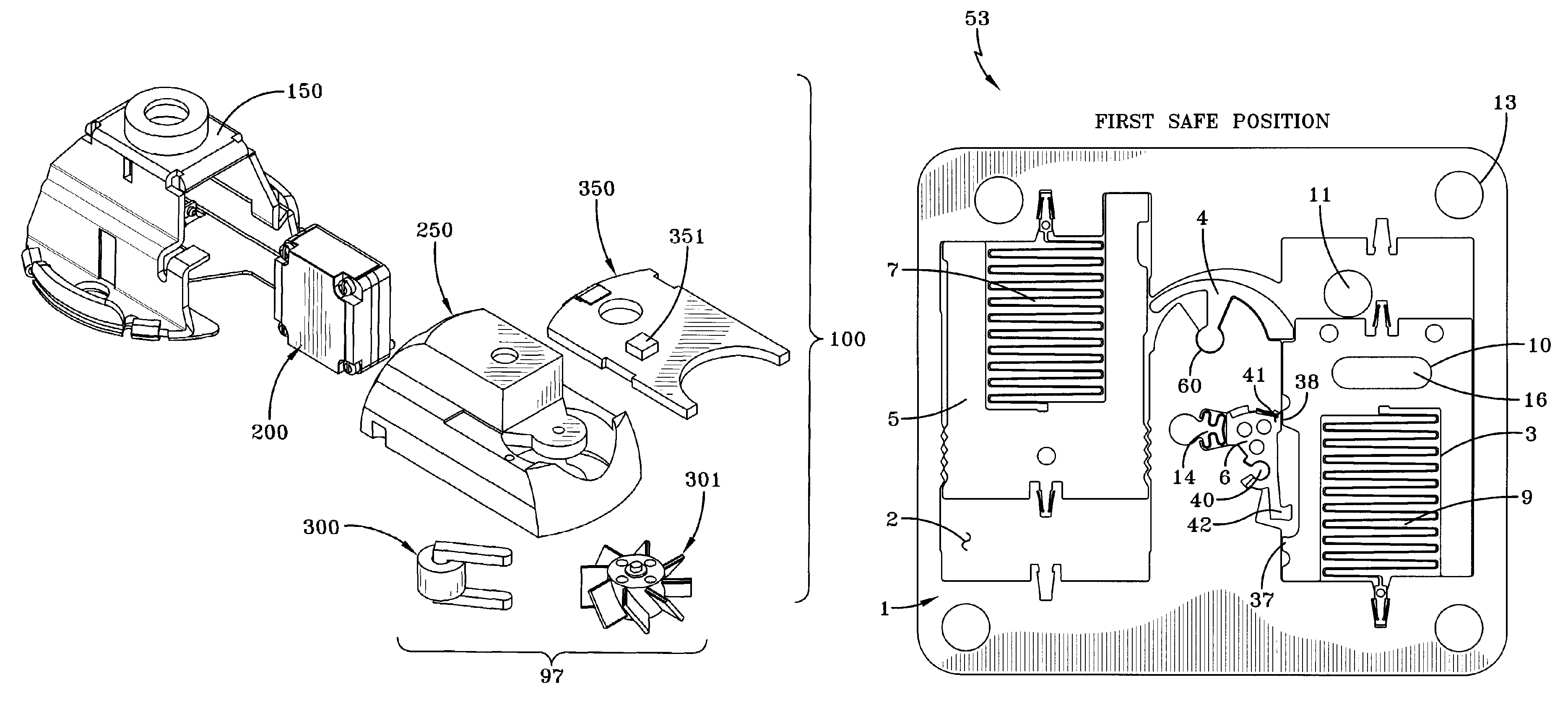
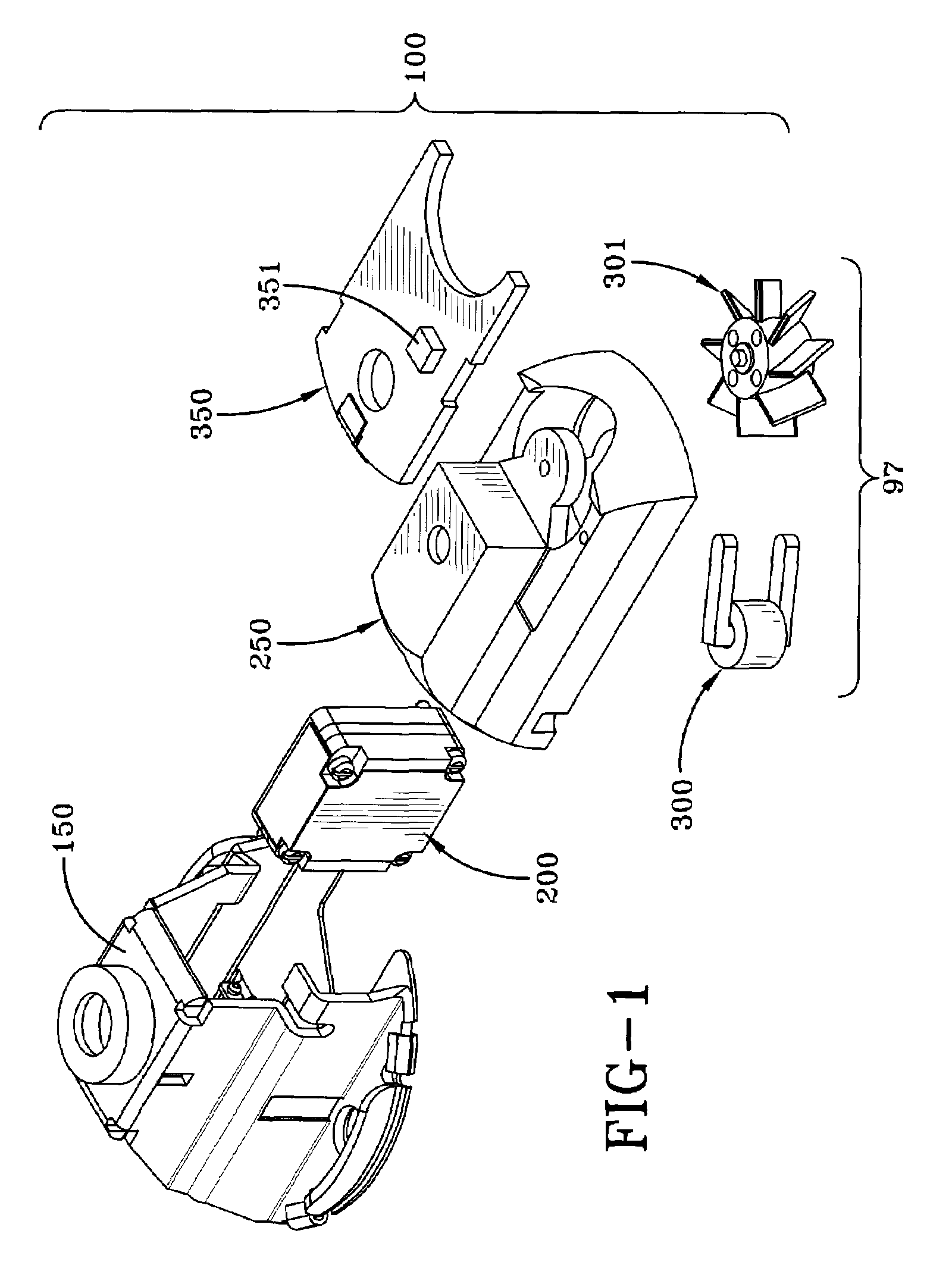
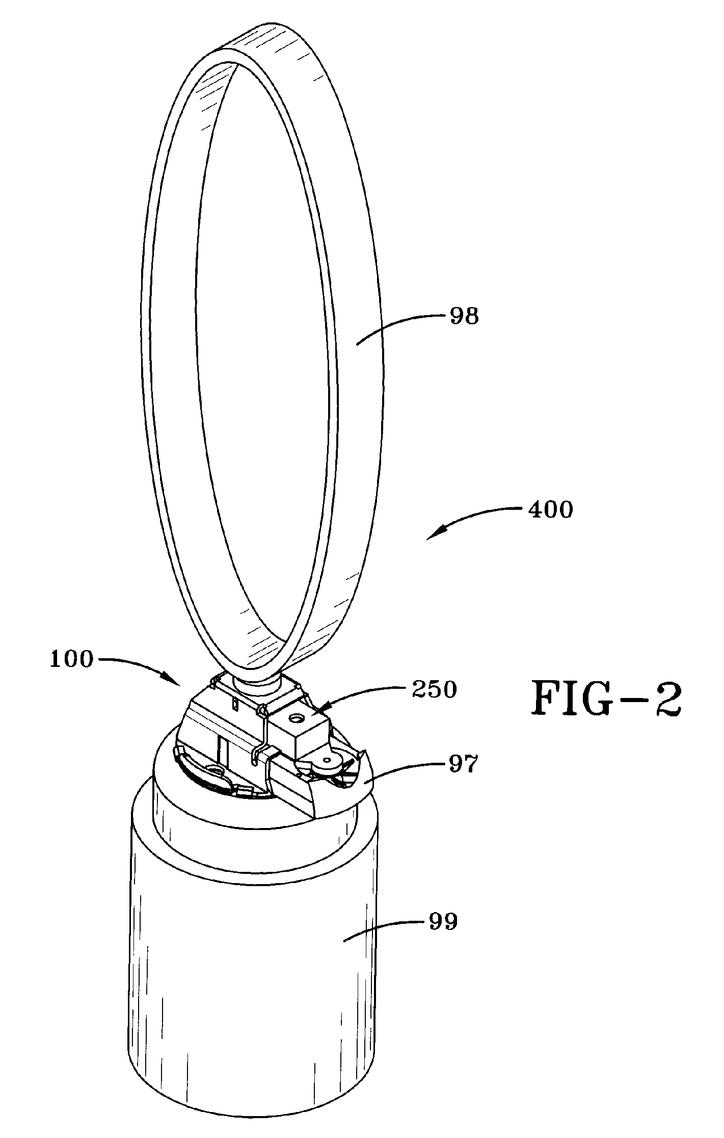
[0049]The invention relates to a submunition (grenade), an electro-mechanical fuze for the submunition and a safety and arming (S&A) device for the fuze. The invention incorporates interrelated mechanical and electronic safety logic for reliability and safety. An important application of the invention is in fuzing for submunition grenades that are deployed by gun-launched “cargo” munitions or grenade-carrying rockets or missiles. The inventive fuze can, in general, perform as the fuze for all high-speed-dispensed submunition grenades launched aboard rockets (e.g., MLRS, Hydra 2.75″, etc.) or gun-launched using cargo rounds (e.g., ERGM), and including submunitions such as EX-1, BLU-97 / B, M74, M77, M85, all DPICM rounds, and involving fuzes such as XM234, M235, etc. The inventive fuze is particularly useful for grenades used in MLRS rockets on Marine HIMARS (high-mobility artillery rocket system) 6×6 truck platforms, especially those carried shipboard, because of its unusually high de...


PUM


Abstract

A fuze for a submunition comprises a fuze housing with a stabilizer ribbon for aerodynamic orientation, a fuze slider released by tension on the stabilizer ribbon, an air-powered electric generator extended into the airstream by the fuze slider and powered in flight by high-speed airflow, a MEMS safety and arming device, a fuze circuit board including an explosive fireset, and an electrically initiated firetrain. The fuze is fixed to and communicates explosively with the end of a grenade warhead.

Description

CROSS-REFERENCE TO RELATED APPLICATIONS[0001]This application claims the benefit under 35 USC 119(e) of U.S. provisional patent application 60 / 522,988 filed on Nov. 30, 2004, which application is hereby incorporated by reference.BACKGROUND OF THE INVENTION[0002]The invention relates in general to submunitions and grenades and, more particularly, to an environmentally energized safety, arming, and detonation device for a submunition, which is more reliable and safer than conventional devices.[0003]Known dual-purpose improved conventional munition (DPICM) grenade fuzes such as the M223 and M234 detonate the grenade warhead on impact with ground or target through use of an inertial stab bolt or firing pin and a stab detonator. The grenades are stacked in a mechanically safe (unarmed) state inside a rocket or “cargo” round. When grenades are stacked in the cargo round, the tip end of the threaded firing pin engages the arming slider and prevents the arming slider from moving into the ar...

Claims


Application Information

Patent Timeline
IPC IPC(8): F42C15/24
CPCF42C15/24
Inventor ROBINSON, CHARLES H.WOOD, ROBERT H.GELAK, MARK R.HOANG, THINH Q.
Owner UNITED STATES OF AMERICA THE AS REPRESENTED BY THE SEC OF THE ARMY
Why Eureka
Try Eureka