Vehicle brake and method for actuating a vehicle brake

a technology for vehicle brakes and brakes, applied in the direction of brake systems, axially engaging brakes, electric vehicles, etc., can solve the problems of requiring electric motors and an additional load on the electrical system, and the entire arrangement is relatively complicated, so as to achieve the effect of fast and reliable activation of the parking braking function

Inactive Publication Date: 2008-01-08
LUCAS AUTOMOTIVE GMBH
View PDF14 Cites 16 Cited by
  • Summary
  • Abstract
  • Description
  • Claims
  • Application Information

AI Technical Summary

Benefits of technology

[0004]The problem of the present invention is to provide a vehicle brake of the initially described type that combines a simple and compact construction with fast and reliable activation of the parking braking function.
[0005]In a vehicle brake of the initially described type, this problem is solved in that the blocking device comprises an electromechanical latching arrangement, which is actuable in such a way that in a latching position it prevents a displacement of the brake piston inside the housing and in a release position it enables the brake piston to move in the housing.
[0008]An advantageous development of the invention provides that two detent elements are actuable by means of the electromechanical actuator, wherein the distance between the detent elements and the pitch of the counterpart detent component designed with a plurality of detent-element working surfaces are tuned in such a way to one another that in the locking position only one of the detent elements is in self-locking engagement with one of the detent-element working surfaces and the, in each case, other detent element in said case engages without self-locking between two adjacent detent-element working surfaces. In this way, it is possible to achieve a doubling of the detent stages, i.e. a refinement of the distances between individual detent positions.
[0011]For reducing the forces arising at the latching arrangement, a development of the invention provides that the blocking element is drive-connected to the counterpart detent component by a gear device, in particular by a planetary gear. In said case, it may be provided that the blocking element is connected in a rotationally fixed manner to a sun wheel of the planetary gear, that moreover the counterpart detent component is connected in a rotationally fixed manner to a planet carrier of the planetary gear and that the ring gear of the planetary gear is formed in or connected in a rotationally fixed manner to the housing. Alternatively, it may be provided that the blocking element is connected in a rotationally fixed manner to a planet carrier of the planetary gear, that moreover the counterpart detent component is connected in a rotationally fixed manner to a sun wheel of the planetary gear and that the ring gear of the planetary gear is formed in or connected in a rotationally fixed manner to the housing. For further reducing the forces arising at the latching arrangement, it may be provided that the planetary gear is of a multi-step design.

Problems solved by technology

For displacement of the actuating rod, according to this patent an electromotive drive is required, thereby lending the entire arrangement a relatively complicated construction.
The required electric motor is moreover an additional load on the electrical system of a motor vehicle.

Method used


Image

  • Vehicle brake and method for actuating a vehicle brake
  • Vehicle brake and method for actuating a vehicle brake
  • Vehicle brake and method for actuating a vehicle brake

Examples


first embodiment

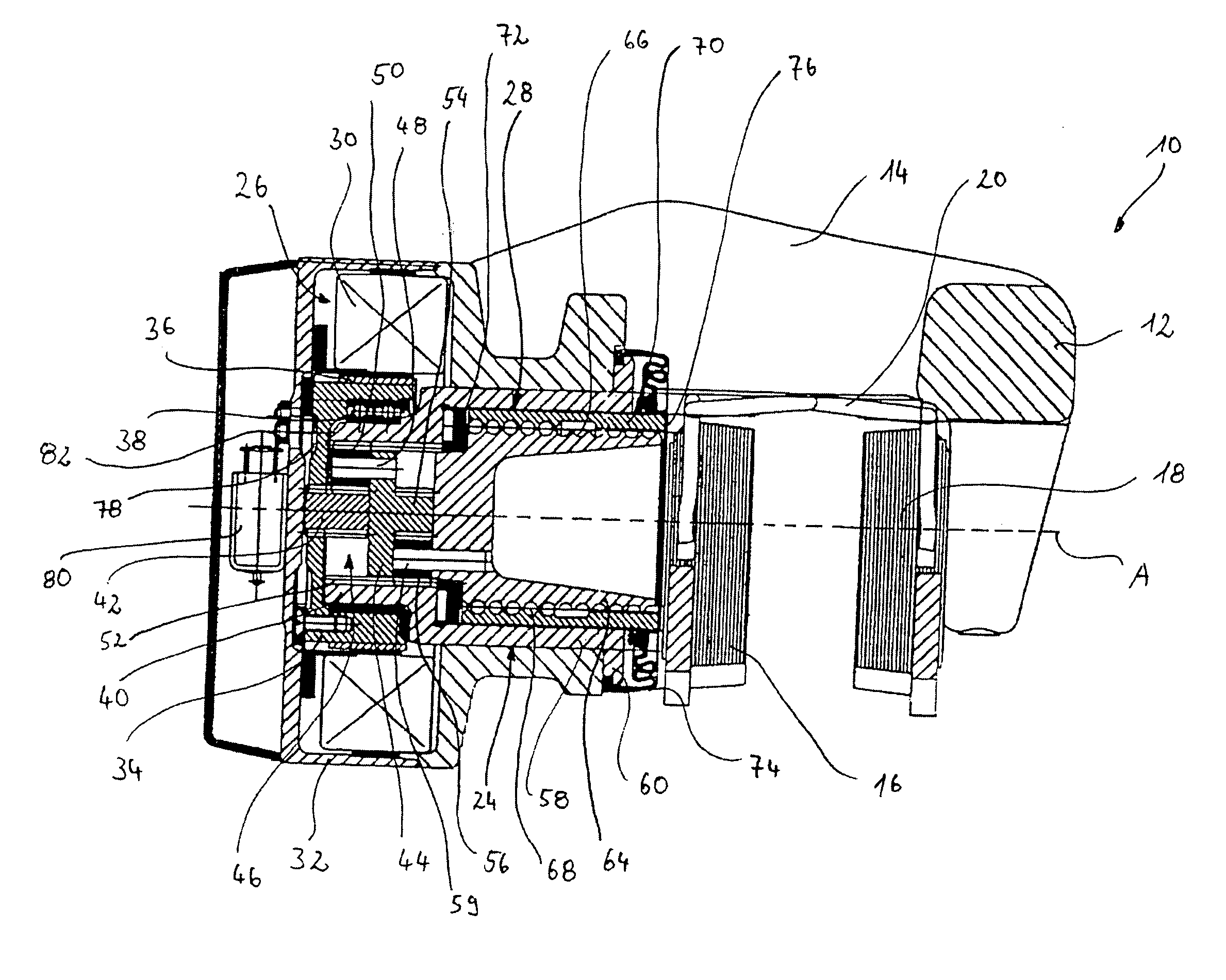
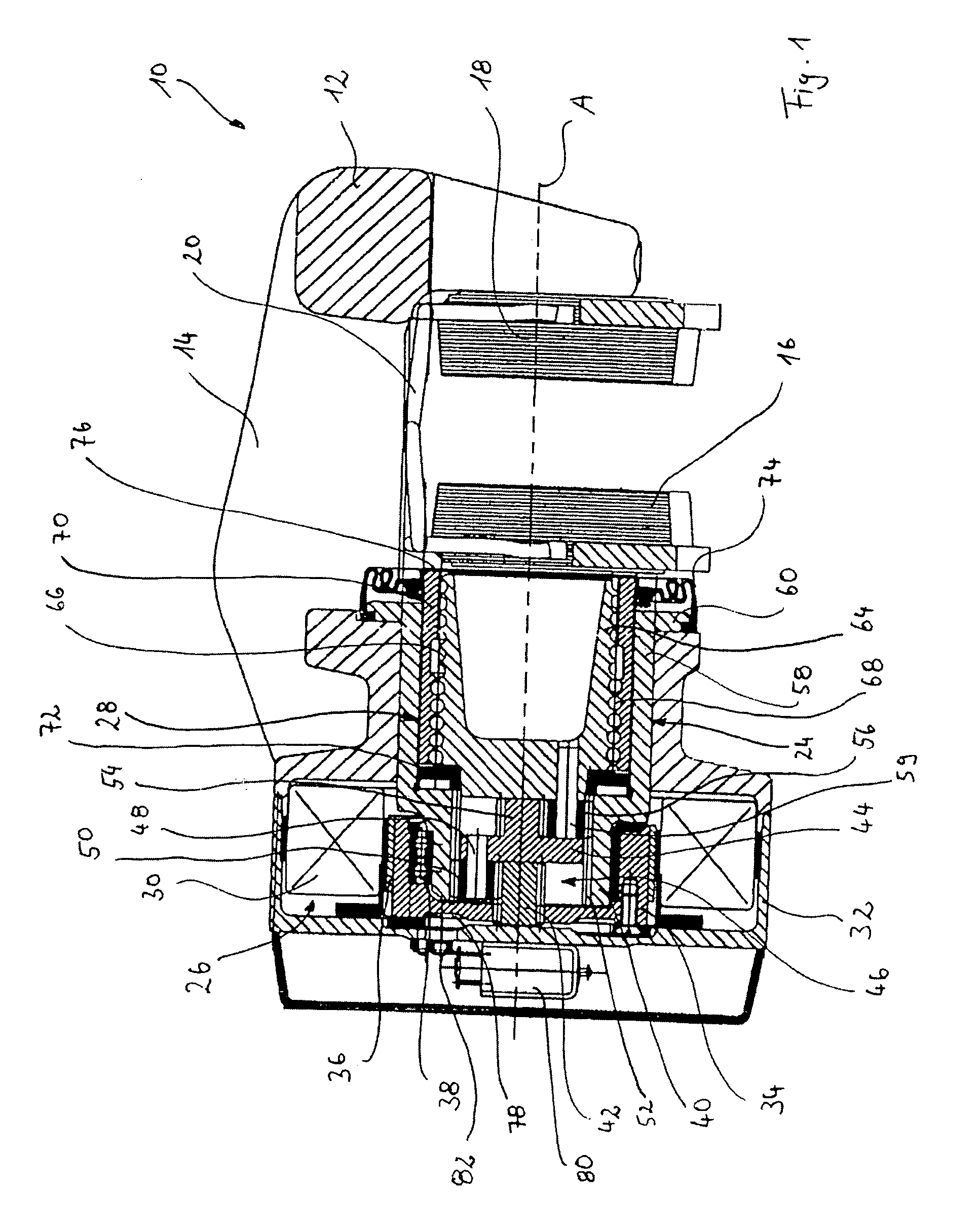
[0027]In FIG. 1 a vehicle brake according to the invention is shown in longitudinal section and generally denoted by 10. The vehicle brake 10, as will be additionally explained below in detail, is actuated electromechanically. It takes the form of a disc brake of the floating caliper type. For this purpose, the vehicle brake 10 comprises a housing 12 with a floating caliper region 14. In the floating caliper region 14 a first brake lining 16 and a second brake lining 18 are disposed. The two brake linings 16 and 18 are resiliently connected to one another by a release play spring 20, wherein the release play spring 20 attempts to push the two brake linings 16 and 18 apart from one another. Accommodated between the two brake linings 16 and 18 is a brake disc (not shown), which is connected at its radially inner region to a vehicle wheel (likewise not shown) that is to be braked. The brake lining 18 is fitted on the floating caliper region 14 of the housing 12 so as to be displaceable...

second embodiment

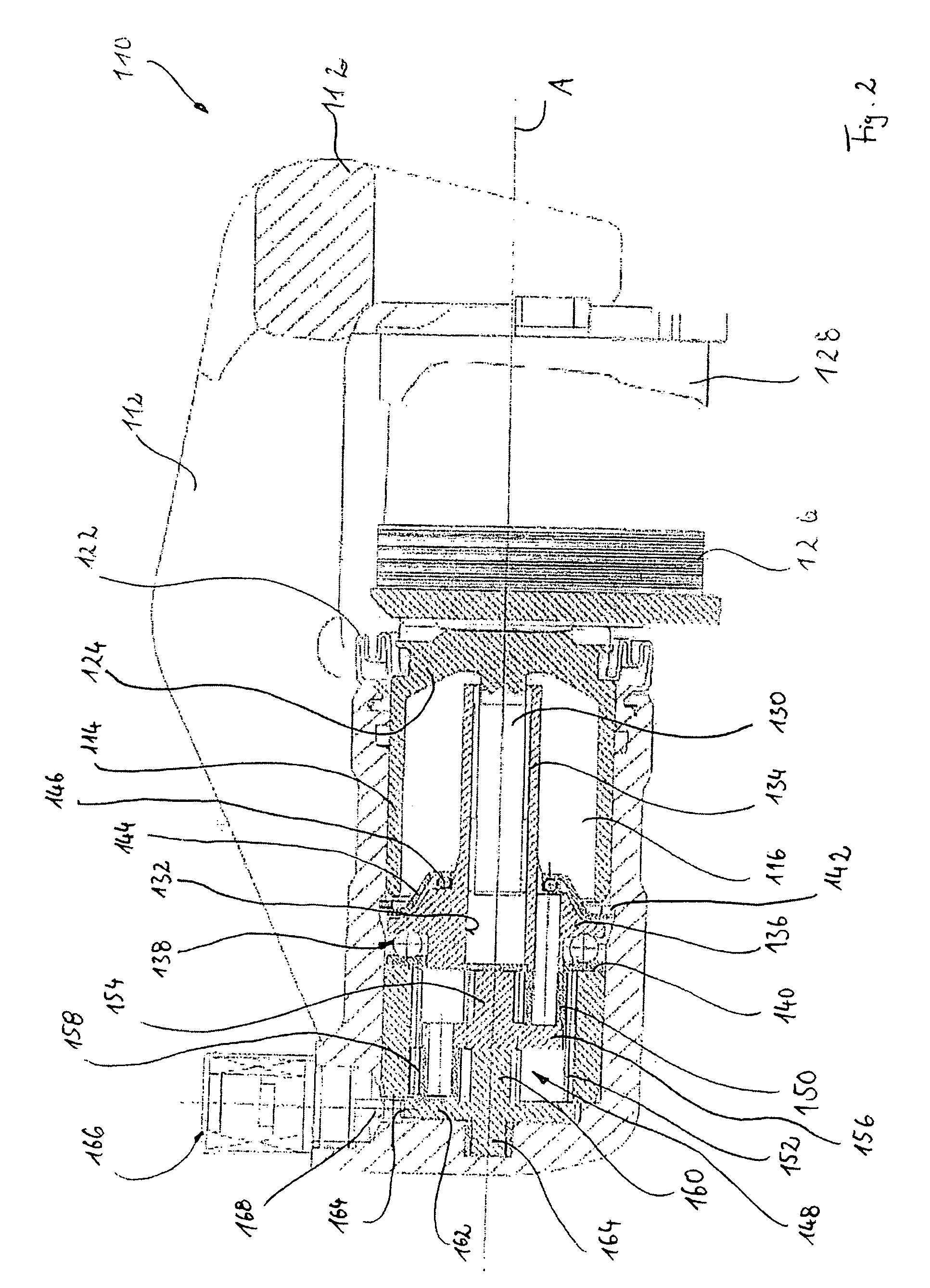
[0036]In FIG. 2 a vehicle brake according to the invention is denoted by 110. The vehicle brake 110 comprises a housing 112, in which a brake piston 114 is guided displaceably in the direction of a piston longitudinal axis A. The brake piston 114 with the housing 112 encloses a fluid chamber 116, to and / or from which hydraulic fluid is feedable and / or dischargeable through a non-illustrated hydraulic fluid line of a hydraulic fluid circuit. The brake piston 114 guided in the housing 112 is connected at its, in FIG. 2, right front end by bellows 122 to the housing 112, so that the housing interior is screened off to prevent dirt from penetrating. Disposed on the front end 124 of the brake piston 114 is a brake lining 126, which is displaceable in the housing 112. Disposed opposite the brake lining 126 is a second brake lining 128, which is likewise displaceable in the housing 112. The brake linings 126 and 128 are supported in the housing 112 in accordance with a conventional floatin...

fourth embodiment

[0053]In the fourth embodiment according to FIGS. 5 to 7, the blocking element 334 is likewise connected by a planetary gear 360 to the detent disk 362. The planetary gear 360 comprises a sun wheel 384 fitted in a rotationally fixed manner on the blocking element, three planet wheels 382 meshing with the sun wheel 384 and supported by bearing pins 390 rotatably on the detent disk 362 serving as a planet carrier, and a sun wheel 386, which is fitted in a rotationally fixed manner in the housing 312 and with which the planet wheels 382 mesh.

[0054]A further characteristic feature of the fourth embodiment according to FIGS. 5 to 7 is that the detent disk 362 is connected by a spiral spring 388 to the housing 312. The spiral spring 388 is tensioned when the brake piston 314 is displaced towards the non-illustrated brake disc and leads to the build-up of a resetting force, which upon release of the brake piston 314 returns the brake piston 314 actively to its basic position shown in FIG. ...


PUM


Abstract

In a vehicle brake comprising a housing, a brake piston, which is accommodated in the housing and on which a brake lining is fitted, and a blocking device, it is provided that the brake piston is displaceable in the housing by means of an actuating device and that the brake piston is securable relative to the housing by means of the blocking device. In this vehicle brake, it is further provided that the blocking device comprises an electromechanical latching arrangement, which is actuable in such a way that in a latching position it prevents a displacement of the brake piston inside the housing and in a release position it enables a movement of the brake piston in the housing.

Description

CROSS-REFERENCE TO RELATED APPLICATIONS[0001]This application is a continuation of International Application No. PCT / EP2004 / 004770 filed May 5, 2004, the disclosures of which are incorporated herein by reference in entirety, and which claimed priority to German Patent Application No. 103 20 884.4 filed May 9, 2003, the disclosures of which are incorporated herein by reference in entirety.BACKGROUND OF THE INVENTION[0002]The invention relates to a vehicle brake comprising a housing, a brake piston, which is accommodated in the housing and on which a brake lining is fitted, and a blocking device, wherein the brake piston is displaceable in the housing by means of an actuating device and wherein the brake piston is securable relative to the housing by means of the blocking device.[0003]Such a vehicle brake is known for example from the European patent EP 0 551 397, and corresponding U.S. Pat. No. 5,148,894 A1, both of which are incorporated by reference herein in entirety. With this ve...

Claims


Application Information

Patent Timeline
Patent Type & Authority Patents(United States)
IPC IPC(8): F16D55/08B60T13/74F16D65/14
CPCF16D55/00F16D2121/24F16D2125/36F16D2127/06
Inventor DANNE, ULRICHGILLES, LEO
Owner LUCAS AUTOMOTIVE GMBH
Why Eureka
Try Eureka