Conversion of synthesized spectral components for encoding and low-complexity transcoding

a spectral component and spectral component technology, applied in the field of audio coding methods and devices, can solve the problems of high cost, inability to create any missing irrelevant information, and high quantization noise of representations with a lower accuracy, so as to improve the quality of transcoded signals and achieve less cost.

Active Publication Date: 2008-01-08
DOLBY LAB LICENSING CORP
View PDF39 Cites 43 Cited by
  • Summary
  • Abstract
  • Description
  • Claims
  • Application Information

AI Technical Summary

Benefits of technology

[0013]It is an object of the present invention to provide coding techniques that can be used to improve the quality of transcoded signals and to allow transcoding equipment to be implemented less expensively.
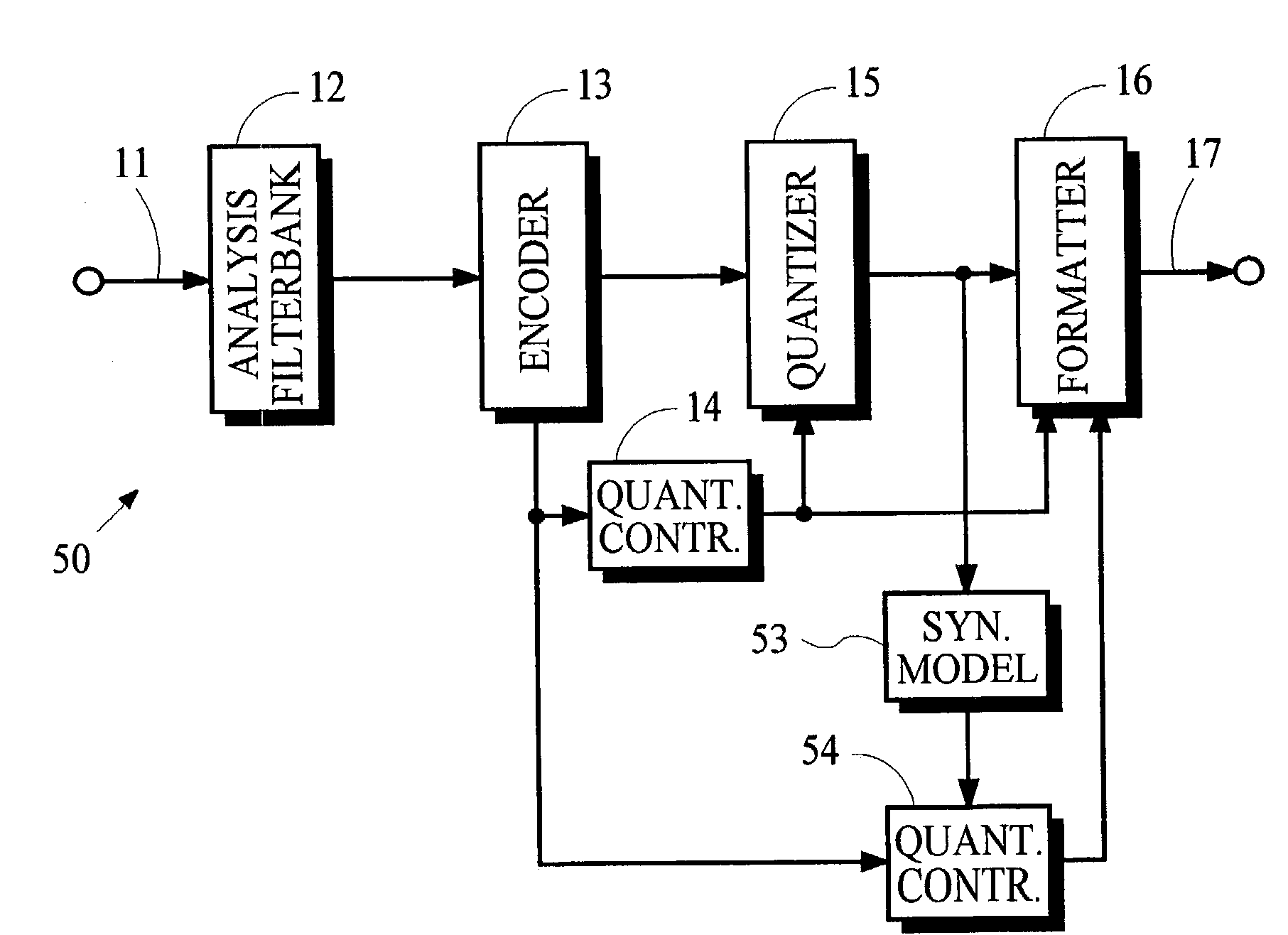
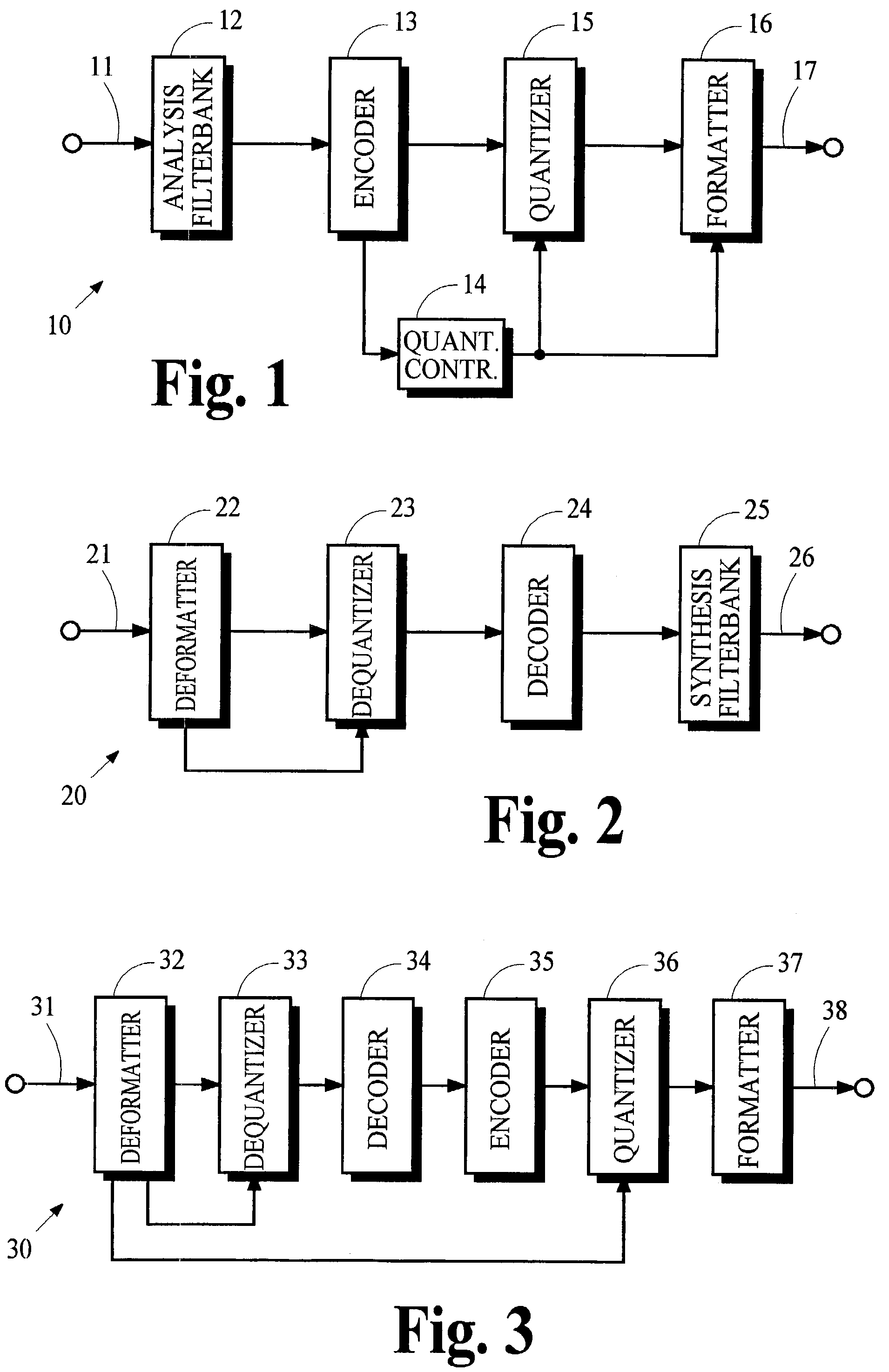
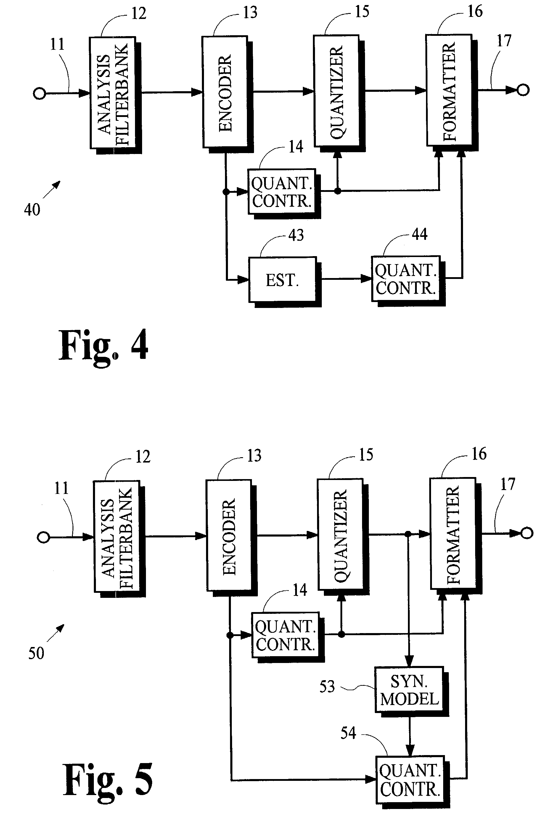
[0014]This object is achieved by the present invention as set forth in the claims. A transcoding technique decodes an input encoded signal to obtain spectral components and then encodes the spectral components into an output encoded signal. Implementation costs and signal degradation incurred by synthesis and analysis filtering are avoided. Implementation costs of the transcoder may be further reduced by providing control parameters in the encoded signal rather than have the transcoder determine these control parameters for itself.

Problems solved by technology

Many communications systems face the problem that the demand for information transmission and recording capacity often exceeds the available capacity.
A perceptual decoder can recreate the missing redundant portions from an encoded signal but it cannot create any missing irrelevant information that was not also redundant.
Representations with a lower accuracy have a higher level of quantization noise.
If a perceptually transparent technique cannot achieve a sufficient reduction in information capacity requirements, then a perceptually non-transparent technique is needed to discard additional signal portions that are not redundant and are perceptually relevant.
The inevitable result is that the perceived fidelity of the transmitted or recorded signal is degraded.
One consequence of further advancements is a potential incompatibility between signals that are encoded by newer coding techniques and existing equipment that implements older coding techniques.
Although much effort has been made by standards organizations and equipment manufacturers to prevent premature obsolescence, older receivers cannot always correctly decode signals that are encoded by newer coding techniques.
Conversely, newer receivers cannot always correctly decode signals that are encoded by older coding techniques.
Conventional transcoding techniques have serious disadvantages when they are used to convert signals that are encoded by perceptual coding systems.
One disadvantage is that conventional transcoding equipment is relatively expensive because it must implement complete decoding and encoding processes.
A second disadvantage is that the perceived quality of the transcoded signal after decoding is almost always degraded relative to the perceived quality of the input encoded signal after decoding.

Method used


Image

  • Conversion of synthesized spectral components for encoding and low-complexity transcoding
  • Conversion of synthesized spectral components for encoding and low-complexity transcoding
  • Conversion of synthesized spectral components for encoding and low-complexity transcoding

Examples


Embodiment Construction

A. Overview

[0021]A basic audio coding system includes an encoding transmitter, a decoding receiver, and a communication path or recording medium. The transmitter receives an input signal representing one or more channels of audio and generates an encoded signal that represents the audio. The transmitter then transmits the encoded signal to the communication path for conveyance or to the recording medium for storage. The receiver receives the encoded signal from the communication path or recording medium and generates an output signal that may be an exact or approximate replica of the original audio. If the output signal is not an exact replica, many coding systems attempt to provide a replica that is perceptually indistinguishable from the original input audio.

[0022]An inherent and obvious requirement for proper operation of any coding system is that the receiver must be able to correctly decode the encoded signal. Because of advances in coding techniques, however, situations arise ...


PUM


Abstract

In an audio coding system, an encoding transmitter represents encoded spectral components as normalized floating-point numbers. The transmitter provides first and second control parameters that may be used to transcode the encoded spectral parameters. A transcoder uses first control parameters to partially decode the encoded components and uses second control parameters to re-encode the components. The transmitter determines the second control parameters by analyzing the effects of arithmetic operations in the partial-decoding process to identify situations where the floating-point representations lose normalization. Exponents associated with the numbers that lose normalization are modified and the modified exponents are used to calculate the second control parameters.

Description

TECHNICAL FIELD[0001]The present invention generally pertains to audio coding methods and devices, and more specifically pertains to improved methods and devices for encoding and transcoding audio information.BACKGROUND ARTA. Coding[0002]Many communications systems face the problem that the demand for information transmission and recording capacity often exceeds the available capacity. As a result, there is considerable interest among those in the fields of broadcasting and recording to reduce the amount of information required to transmit or record an audio signal intended for human perception without degrading its perceived quality. There is also an interest to improve the perceived quality of the output signal for a given bandwidth or storage capacity.[0003]Traditional methods for reducing information capacity requirements involve transmitting or recording only selected portions of the input signal. The remaining portions are discarded. Techniques known as perceptual encoding typ...

Claims


Application Information

Patent Timeline
Patent Type & Authority Patents(United States)
IPC IPC(8): G10L19/14G10L21/00G10L19/02
CPCG10L19/173G10L19/02
Inventor LENNON, BRIAN TIMOTHYTRUMAN, MICHAEL MEADANDERSEN, ROBERT LORING
Owner DOLBY LAB LICENSING CORP
Why Eureka
Try Eureka