
Pultruded trim members

a technology of trim members and pulverized parts, which is applied in the field of pulverized trim members, can solve the problems of inability to paint vinyl at all, labor required to install several component parts, and needing regular repainting

Inactive Publication Date: 2008-01-15
PN II
View PDF41 Cites 22 Cited by
  • Summary
  • Abstract
  • Description
  • Claims
  • Application Information

AI Technical Summary

Benefits of technology

[0008]The present invention includes improved methods for fabricating cornice assemblies and other trim members used in house construction. The cornice assemblies and trim members are fabricated through a process of pultrusion. Improved cornice assemblies are disclosed, which include at least a fascia, a soffit and a frieze with crown molding, all of whic

Problems solved by technology

Aluminum or vinyl is a preferred material because of the high maintenance of wood trim pieces, which require repainting every few years (but in fact, vinyl cannot be painted at all).
One problem associated with decorative and protective cornice assemblies is the labor required to install the several component parts, such as the fascia, the soffit, the frieze, and decorative moldings associated therewith.
A second problem occurs when wood is used, which may rot and which requires regular repainting.
A third problem is denting of aluminum products, and a fourth problem is expanding and contracting of aluminum and vinyl.
This practice adds significant time and expense to the construction of a conventional building structure.
In addition, a problem associated with aluminum or vinyl cornice assemblies is the shearing of the fasteners used to fasten the cornice assembly or the enlarging of the holes created for fastening the assembly to the building structure.
This shearing / enlarging problem is due to the relatively large amount of expansion and contraction due to temperature or moisture variations, which also causes buckling of the aluminum or vinyl material.
As a result, the cornice assembly may become detached from the building structure or may appear warped.
This process is time-consuming, labor-intensive, and difficult to attain professional looking results.

Method used


Image

  • Pultruded trim members
  • Pultruded trim members
  • Pultruded trim members

Examples


Embodiment Construction

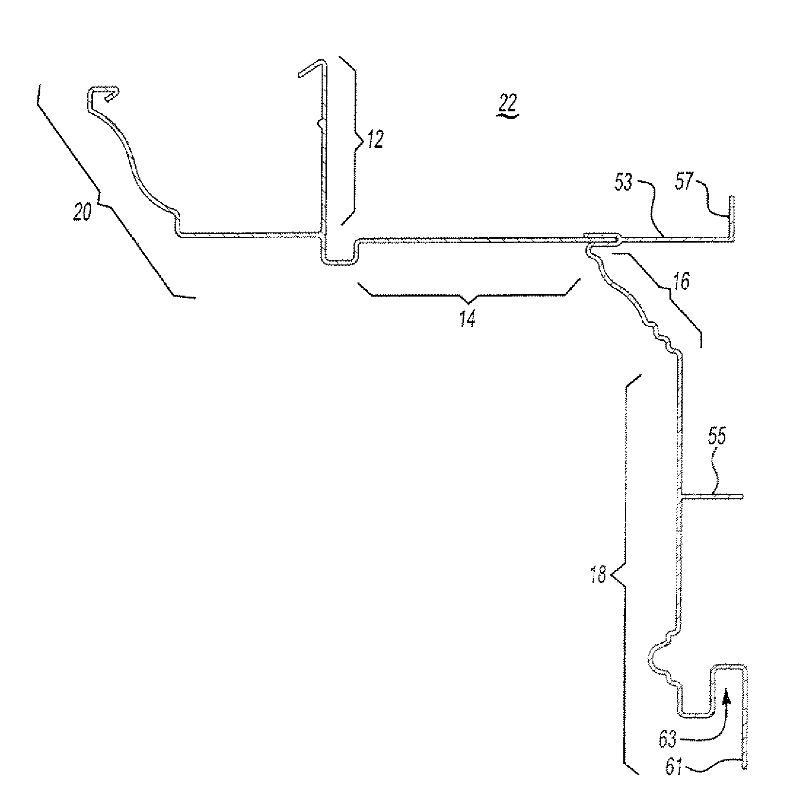
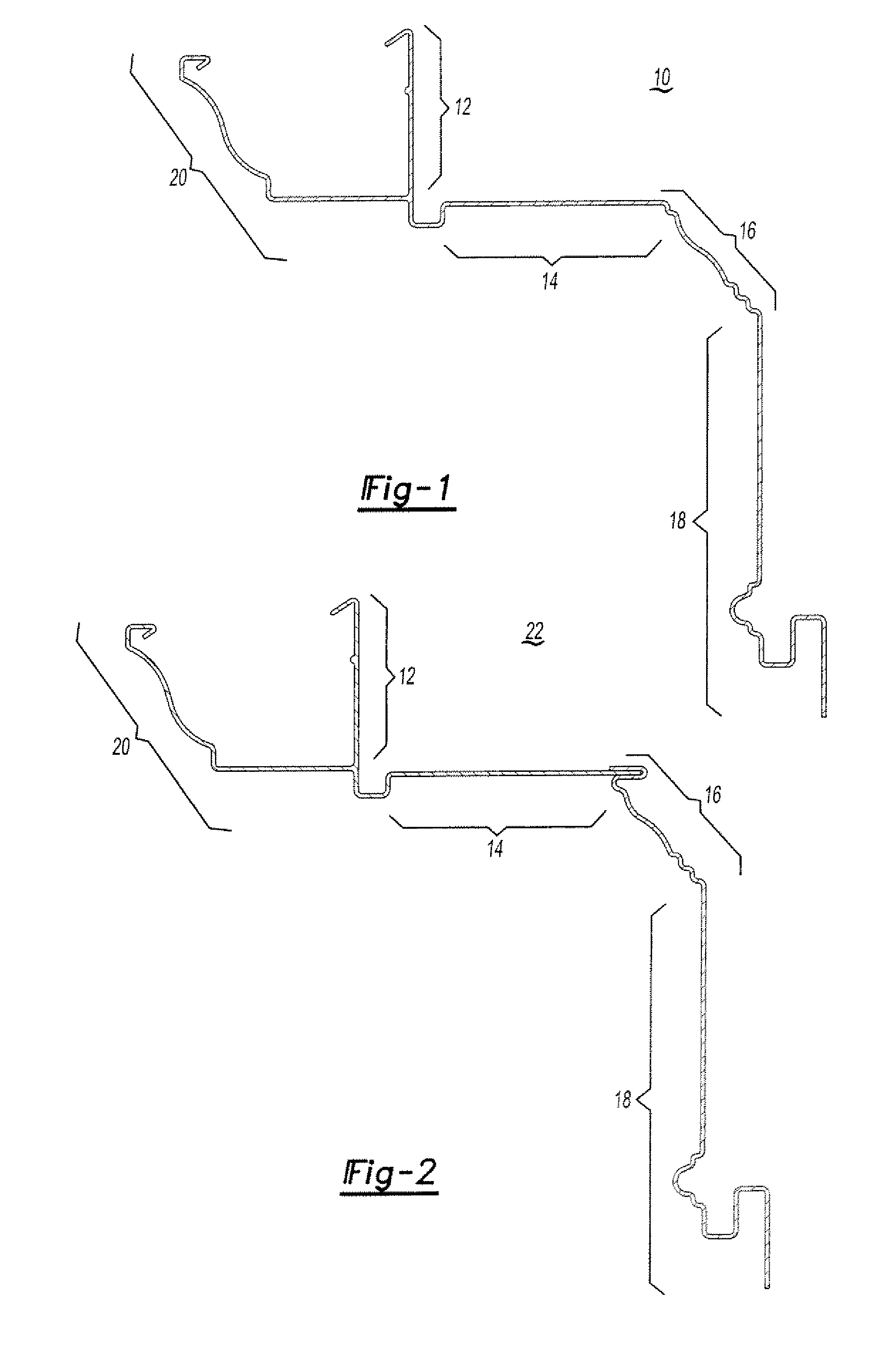
[0025]Referring now to FIG. 1, a cornice assembly 10 according to the invention is shown. The cornice assembly 10 includes portions a facia 12, a soffit 14, a crown 16, and a frieze 18. Optionally, the cornice assembly may also include a gutter 20 in which case the facia 12 forms the back side of the gutter 20.

[0026]A significant advantage may be gained through a unitary construction (formed as one piece) of the cornice assembly 10 in terms of the amount of labor needed to install the cornice assembly 10. With a unitary construction, effort need only be spent on attaching the cornice assembly 10 to the building structure, while effort spent on fabricating the cornice assembly 10 is completely eliminated.

[0027]The cornice assembly 10 may be used in with walls made of any suitable outer sheathing building material known in the art, such as plywood, fiber board, celotex, OSB (oriented strand board) and the like.

[0028]In a second embodiment, as best seen in FIG. 2, the cornice assembly ...


PUM

PropertyMeasurementUnit
Temperatureaaaaaaaaaa

Abstract

The present invention is an improved method of making cornice assemblies and other trim members utilizing the process of pultrusion. The cornice assemblies and the other trim members made by the method of the present invention exhibit superior strength to weight ratios, low expansion and contraction due to changes in temperature and humidity, as well being less labor intensive to install.

Description

FIELD OF THE INVENTION[0001]The invention relates to building structures, and more particularly to trim members for protecting, covering and decorating the area from the base of the roof to the upper portion of the outer wall of a building structure, such as a home or office or other commercial building, where the trim members are manufactured by pultrusion.BACKGROUND OF THE INVENTION[0002]In the United States, most residential or light weight-building systems employ wood or metal rafters, which extend from six to twenty-four inches beyond the outer wall. The outer wall is typically constructed of masonry or wood construction. Typically, the rafters and the sub-fascia (a member that connects the rafter ends together) support roof decking which forms the base of the roof. Shingles or other roofing materials cover the roof decking. Typically, the entire area from the lower edge of the roof decking to the upper portion of the outer wall of the building structure is covered with a corni...

Claims


Application Information

Patent Timeline
IPC IPC(8): B29C47/08E04D13/064E04D13/158
CPCE04D13/064E04D13/158E04D13/1585E04F13/073Y10T29/49616Y10T29/49629Y10T29/49623E04D13/15E04F13/007E04F13/0733E04F13/076E04F13/21E04F13/26E04F2201/0107E04F2201/023E04F2203/02
Inventor PULTE, WILLIAM J.
Owner PN II
Learn More