Partially reflective surface antenna

a technology of partially reflective surface and antenna, which is applied in the direction of antenna details, electrically short antennas, antennas, etc., can solve the problems of limiting the transmission distance of high frequency signals, the ratio of the side lobe portion to the whole waveform cannot be further decreased, and the gain of the partially reflective surface antenna cannot be continuously increased, so as to reduce the energy ratio of the side lobe portion to the whole waveform, reduce the possibility of high frequency signals suffering interference, and prolong the transmission distance of high frequency

Inactive Publication Date: 2008-01-15
TATUNG UNIVERSITY +1
View PDF3 Cites 8 Cited by
  • Summary
  • Abstract
  • Description
  • Claims
  • Application Information

AI Technical Summary

Benefits of technology

[0011]Therefore, by having two different kinds of arrangement of the antenna array disposed on the surface of the reflective board, the partially reflective surface antenna of the present invention can reduce the energy ratio of the side lobe portion of the transmitted high frequency signals and centralize the energy of the transmitted high frequency signals into its main lobe portion, in order to elongate the distance that the high frequency signal can be transmitted and minimize the possibility of the high frequency signal suffering interference. Furthermore, the gain of the partially reflective surface antenna of the present invention is raised higher than that of the conventional partially reflective antenna, so the antenna module having the partially reflective surface antenna of the present invention can have optimum operation efficiency.

Problems solved by technology

However, the high frequency signals transmitted by these partially reflective surface antennas still have obvious levels of the side lobe portion, and the ratio of the side lobe portion to the whole waveform cannot be further decreased.
This drawback prevents the partially reflective surface antenna from providing high frequency signals whose energy is centralized at the portion in the main beam direction, and thus limits the transmission distance of the high frequency signals.
Furthermore, the gain of the partially reflective surface antenna cannot be continuously increased as the area of the reflective board increases.
However, the ratio of the side lobe portion of the high frequency signal transmitted by the conventional partially reflective surface antenna 1 cannot be further decreased and the gain of the conventional partially reflective surface antenna 1 cannot be further increased, either.

Method used


Image

  • Partially reflective surface antenna
  • Partially reflective surface antenna
  • Partially reflective surface antenna

Examples


Embodiment Construction

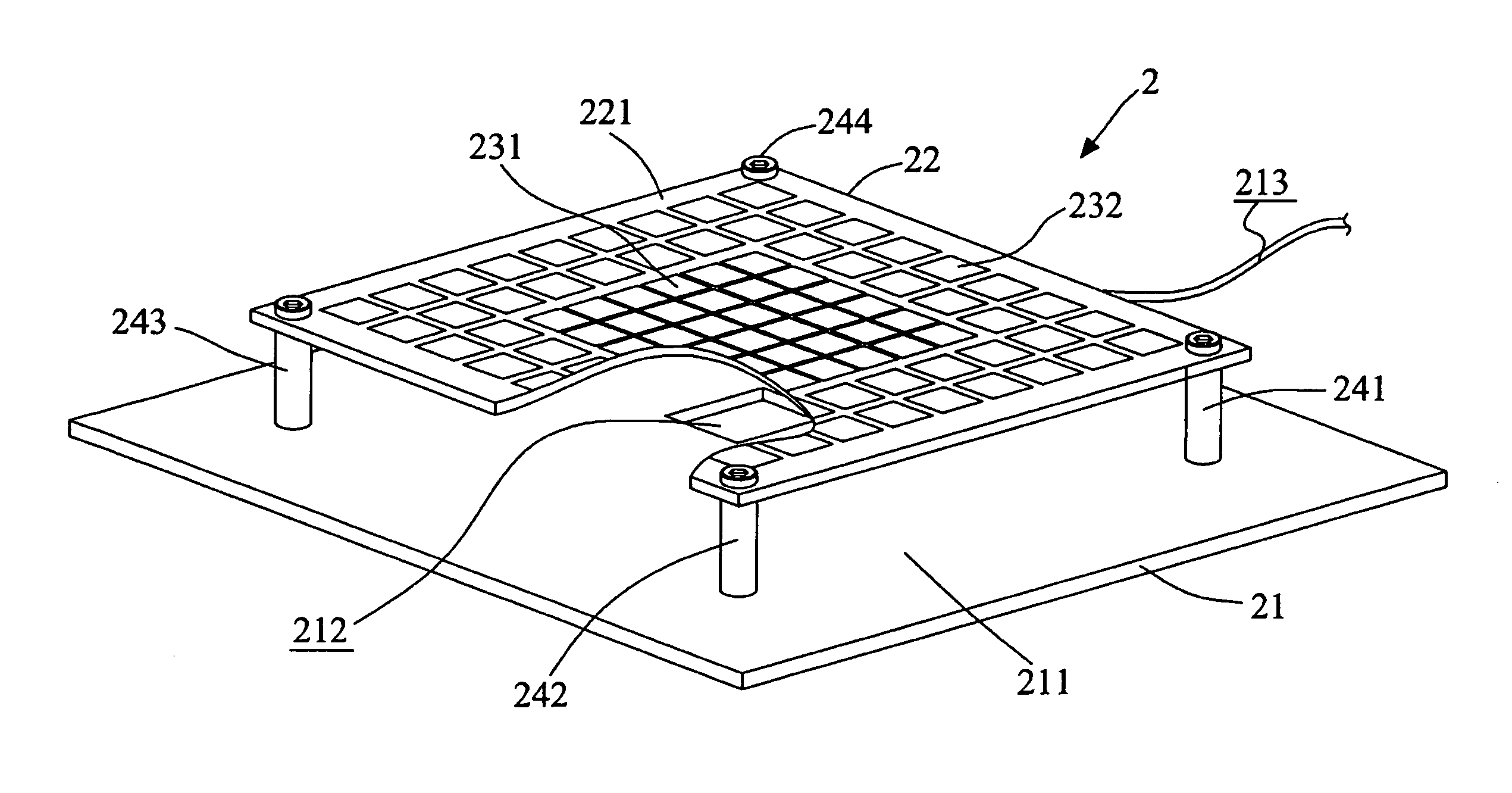
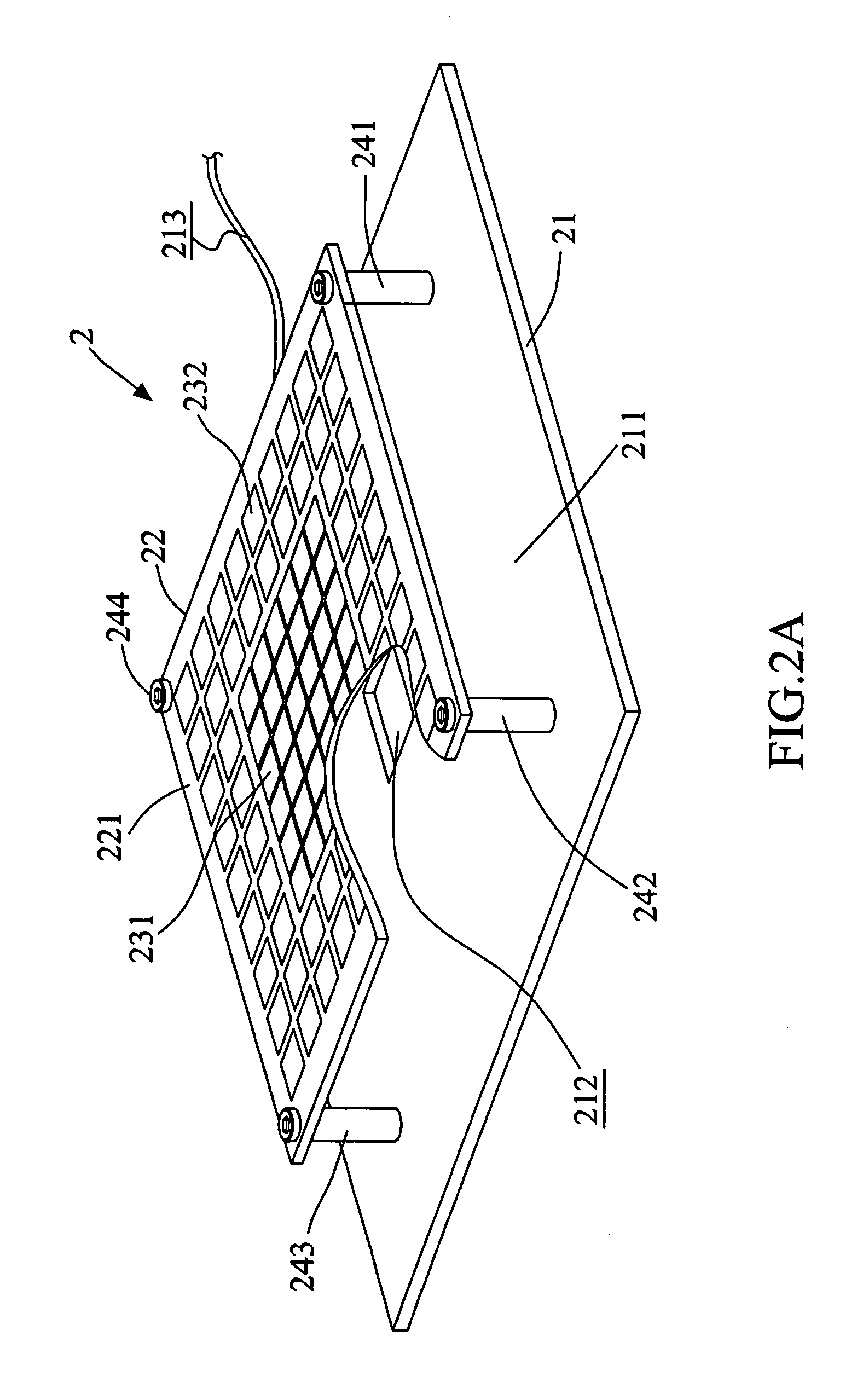
[0030]FIG. 2A is a perspective schematic drawing of the partially reflective surface antenna according to the first preferred embodiment of the present invention, wherein the partially reflective surface antenna 2 comprises a substrate 21 and a reflective board 22. Both of them are composed of microwave substrates made of the FR-4 materials with a thickness of 0.8 mm. The reflective board 22 is supported by a first supporting rod 241, a second supporting rod 242, a third supporting rod 243, and a fourth supporting rod 244. As a result, a resonant distance between the reflective board 22 and an upper surface 211 of the substrate 21 is maintained. The length of the resonant distance is determined with relation to the design frequency of the partially reflective surface antenna 2 of the present invention. That is, when the design frequency of the partially reflective surface antenna 2 of the present invention is 9.3 GHz, the resonant distance is about 1.68 cm; and when the design frequ...


PUM


Abstract

The present invention relates to a partially reflective surface antenna and, more particularly, to a partially reflective surface antenna including a reflective board composed of arrays of microstrip antennas, and has advantages of low side lobe and high gain. It comprises: a substrate with an upper surface having a signal transmitting notch for transmitting and receiving a high frequency signal; a reflective board for partially reflecting the high frequency signal; and a plurality of supporting elements for supporting the reflective board on the substrate. The reflective board has a second antenna array and a first antenna array surrounded by the second antenna array, wherein the first and the second antenna array are composed of a plurality of first microstrip reflective units and a plurality of second microstrip reflective units, respectively. Besides, the distance between the first microstrip reflective units is smaller than the distance between the second microstrip reflective units.

Description

BACKGROUND OF THE INVENTION[0001]1. Field of the Invention[0002]The present invention relates to a partially reflective surface antenna and, more particularly, to a partially reflective surface antenna that includes a reflective board composed of arrays of microstrip antennas, and has the advantages of low side lobe and high gain.[0003]2. Description of Related Art[0004]Recently, in the military or civil application fields, a partially reflective surface antenna having a partially reflective surface (PRS), which is composed of arrays of microstrip antenna, has been used frequently. These partially reflective surface antennas have low profile, and can be manufactured by using printed circuit boards (PCB).[0005]However, the high frequency signals transmitted by these partially reflective surface antennas still have obvious levels of the side lobe portion, and the ratio of the side lobe portion to the whole waveform cannot be further decreased. This drawback prevents the partially refl...

Claims


Application Information

Patent Timeline
Patent Type & Authority Patents(United States)
IPC IPC(8): H01Q1/38H01Q21/00
CPCH01Q15/0006H01Q15/0013
Inventor CHANG, THE-NANCHIU, CHIH-HSIEN
Owner TATUNG UNIVERSITY
Why Eureka
Try Eureka