Process photometer

a photometer and process technology, applied in the field of process photometers, can solve the problems of increasing the cost associated with the construction and maintenance of the photometer, unable to monitor the production process, and not being able to achieve the desired diversion in many production environments

Inactive Publication Date: 2008-01-22
BAYER MATERIALSCINECE
View PDF15 Cites 16 Cited by
  • Summary
  • Abstract
  • Description
  • Claims
  • Application Information

AI Technical Summary

Benefits of technology

[0010]It is an object of the present invention to provide a photometer with a minimum number of moving components subject to excessive mechanical wear.
[0011]It is another object of the present invention to provide a photometer that maximizes total optical throughput for optimum signal to noise ratio, and minimizes alignment criteria for stable, low maintenance operation.
[0012]It is also an object of the present invention to optimize component layout to reduce stress and strain on optical components that would affect alignment and stability.
[0014]It is another object of the present invention to provide a photometer that can be easily installed in a chemical production unit next to the sample point of interest by packaging the photometer in a small housing that provides an explosion proof rating for operation in areas with Class I Division 1 Groups B,C,D classification without additional gas purging or electrical interlocks.
[0015]It is an additional object of the present invention to provide a photometer with enough wavelength specific band-pass filters that it is possible to monitor a chemical production process in-line where a spectrometer scanning a continuum of wavelengths and employing chemometrics was previously required.

Problems solved by technology

Such diversion is not, however, desirable in many production environments.
This system is not, however, capable of monitoring a production process as that process is being conducted.
The use of multiple detectors, however, increases the costs associated with the construction and maintenance of the photometer.
In addition, the use of beam splitters to direct a portion of the electromagnetic radiation to each detector reduces the total signal that would be available if only one detector were used.

Method used


Image

  • Process photometer
  • Process photometer
  • Process photometer

Examples


example

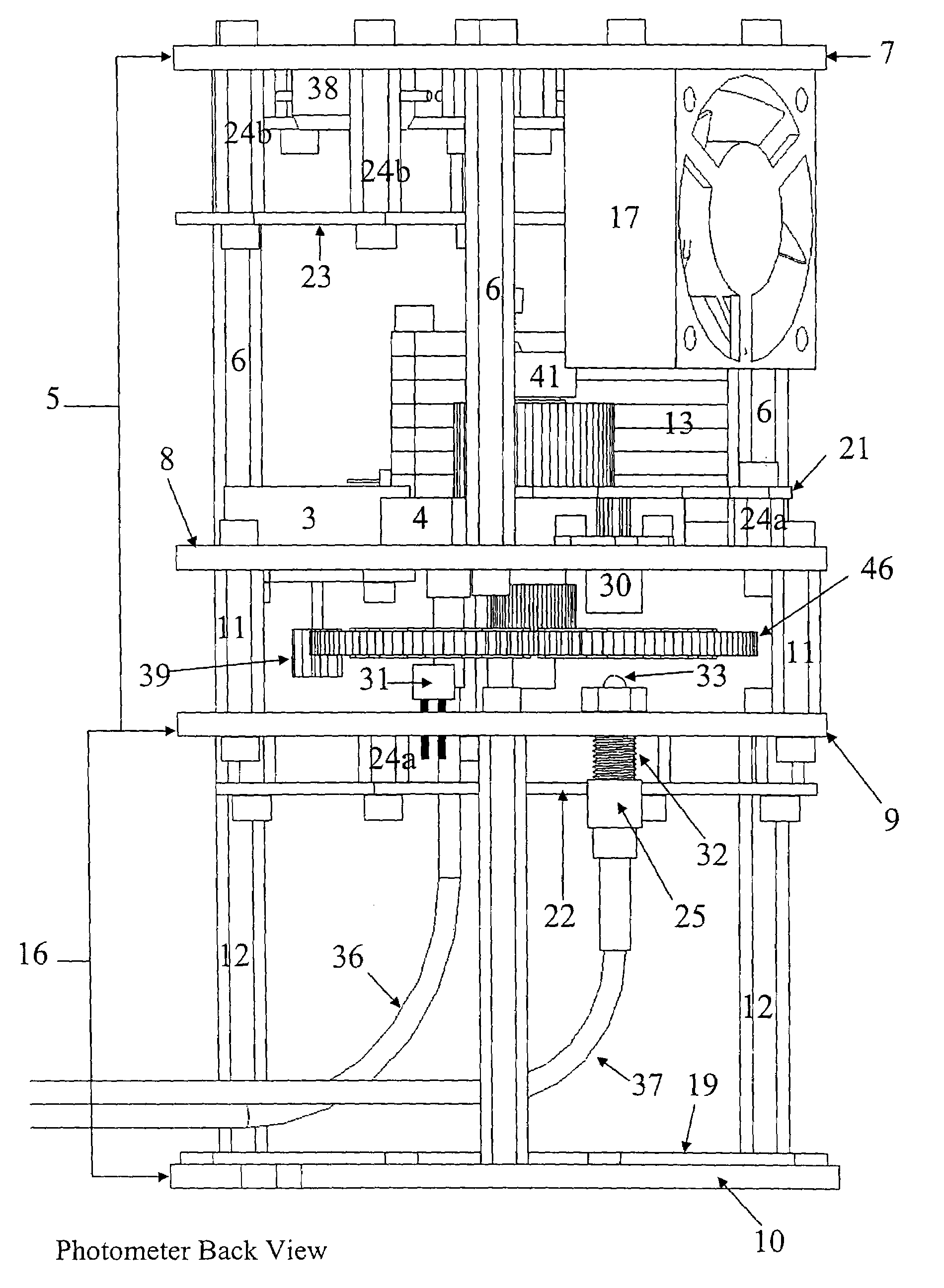
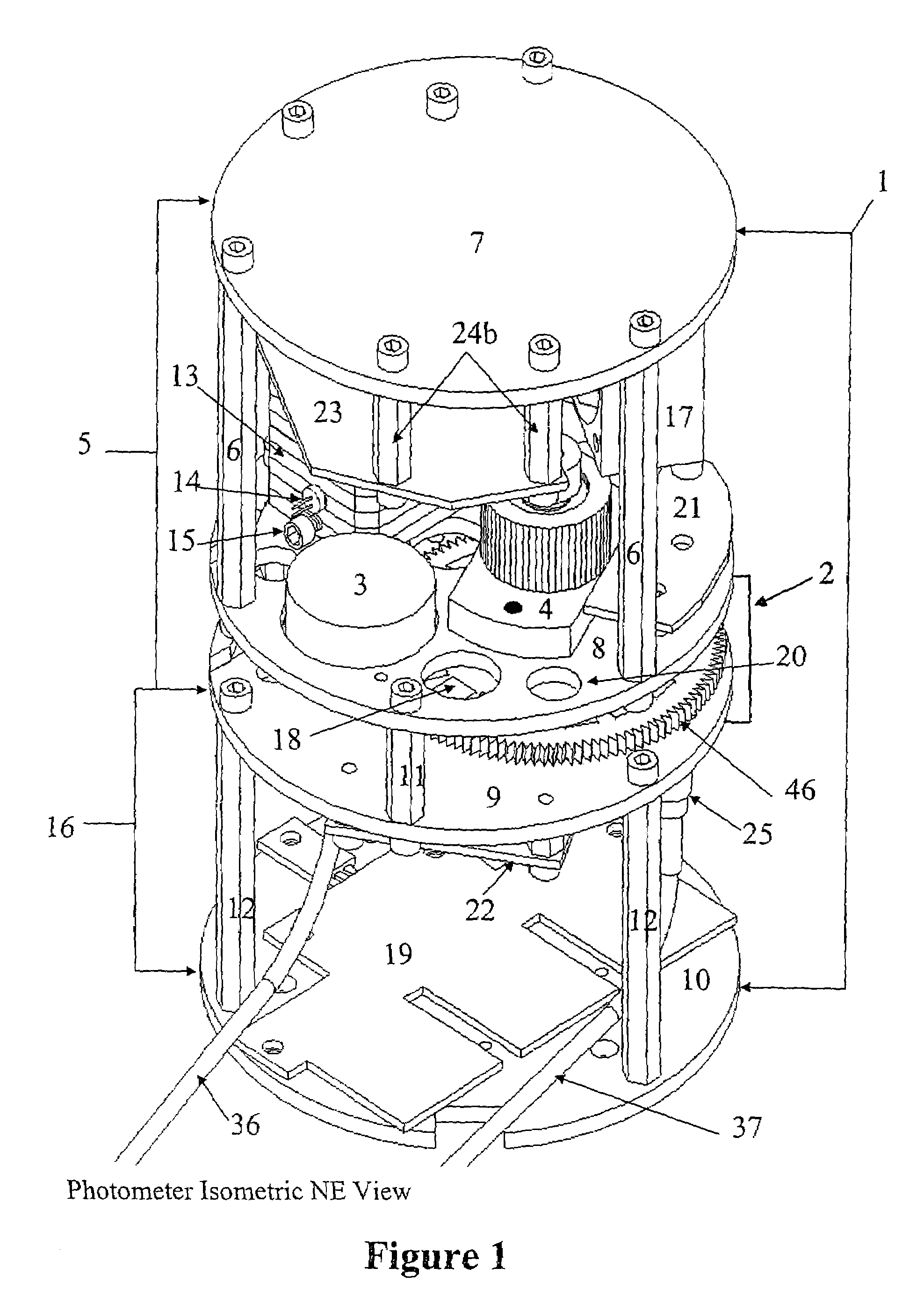
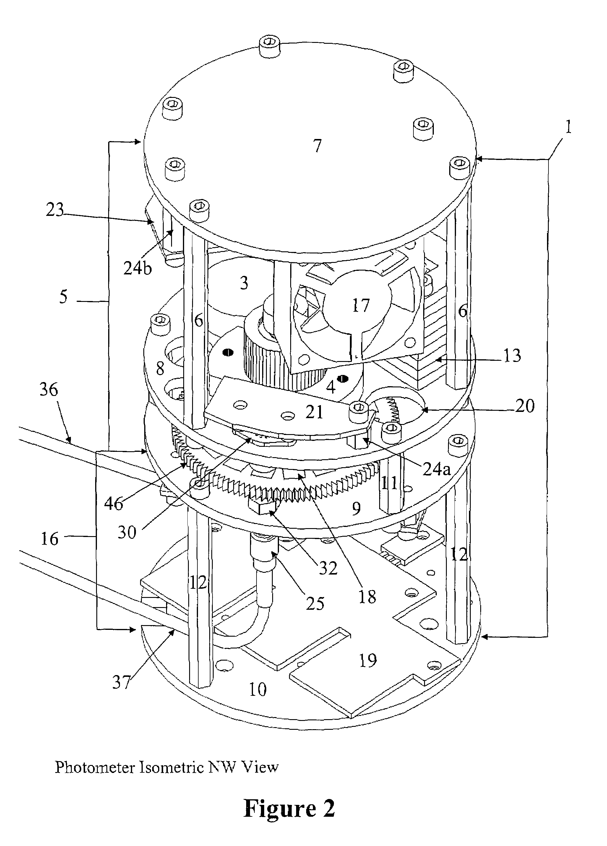
[0056]A device corresponding to that shown in FIGS. 1-9 utilizing the chopped radiation assembly disclosed in Applicants' co-pending application U.S. Ser. No. 10 / 983,404 filed Nov. 8, 2004 was constructed of the materials listed below and housed in an explosion proof ADALET# XIHLDCX Class I Division 1 Groups B,C,D Enclosure.[0057]Filter wheel Assembly 2 was constructed of the following materials:[0058]Bearing housing 4 A housing designed to mount two 0.625 inches (1.588 cm) outside diameter by 0.196 inches (0.498 cm) high bearings spaced 0.163 inches (0.414 cm) apart which is made of aluminum.[0059]Shaft 31 A shaft measuring 0.25 inches (0.635 cm) in diameter and 1.75 inches (4.445 cm) long made of 303 stainless steel.[0060]Set Screw Collar 41 A ring having an inner diameter of 0.25 inches (0.635 cm), an outer diameter of 0.5 inches (1.27 cm), a height of 0.25 inches (0.635 cm) with 6 / 32-thread steel set screw made of aluminum.[0061]Spacer(s) 42a A 0.063 inches long tube with an inn...


PUM

PropertyMeasurementUnit
temperatureaaaaaaaaaa
resonance frequencyaaaaaaaaaa

Abstract

A process photometer which includes an insulated and a non-insulated compartment. The insulated compartment is maintained at a relatively constant, elevated temperature. The radiation source, a rotatable filter wheel, a radiation detector, and a means for converting analog output to a digital signal are among the components within the insulated compartment. The non-insulated compartment houses a power supply.

Description

BACKGROUND OF THE INVENTION[0001]The present invention relates to a process photometer for monitoring a production process in which such photometer is used.[0002]In-line monitoring of chemical processes makes it possible to reduce production cycle time, improve the safety of such processes and reduce waste. A number of methods for such monitoring with conventional analytical devices have been disclosed in the literature. Two general approaches have been taken in developing such monitoring processes. In one approach, the amount of energy absorbed by a sample or selected material is measured and compared to one or more pre-established standards. Examples of this approach may be found in U.S. Pat. Nos. 5,151,474; 5,170,056; and 5,763,883.[0003]U.S. Pat. No. 5,151,474, for example, discloses a polyolefin polymerization process in which the rate of addition of the principal monomer is controlled on the basis of a vibrational spectroscopy analysis (e.g., Fourier Transform infrared spectro...

Claims


Application Information

Patent Timeline
Patent Type & Authority Patents(United States)
IPC IPC(8): G01N21/25
CPCG01J1/02G01J1/0252G01J1/0271G01N21/0332G01N21/272G01N21/359G02B26/007G02B26/008G02B26/04G01J1/0425G01J1/0488G01N2021/3174G01N2201/084
Inventor HUNT, ROBERT N.KHETTRY, ATULVILA, MATTHEW R.
Owner BAYER MATERIALSCINECE
Why Eureka
Try Eureka