Image reading apparatus and image reading system equipped with the image reading apparatus

a reading apparatus and image technology, applied in the field of image reading apparatus and image reading system, can solve the problems of increasing the overall size of the electronic device, troublesome to satisfactorily read detectable object images, fingerprints, etc., and achieve the effect of enlargement of the electronic device and favorable reading

Active Publication Date: 2008-01-22
ORTUS TECH
View PDF18 Cites 99 Cited by
  • Summary
  • Abstract
  • Description
  • Claims
  • Application Information

AI Technical Summary

Benefits of technology

[0010]The present invention has been made in view of the circumstances mentioned above. Accordingly, the present invention provides an image reading apparatus and an image reading system comprising an image reading apparatus which has the advantages of (1) being able to favorably read a detectable object image, for example, a fingerprint, (2) the size of the image reading apparatus can be made smaller while still being able to read a detectable object and (3) the resulting overall enlargement size of the electronic device in which this image reading apparatus is installed can be controlled.

Problems solved by technology

As for an electrostatic capacity type configuration mentioned above, although the detection sensor area where a detectable object is placed for reading an object image can be formed in a thin and lightweight construction, this type of image reading apparatus is highly susceptible to static electricity damage of the detection sensor by a static electricity charge from a detectable object.
For this reason, when considering the size of an image reading apparatus in such a configuration which requires an area of sufficient size for reading detectable object images, such as fingerprints, etc., there is a persistent problem that the overall size of the electronic device will increase.
In that case, it becomes troublesome to satisfactorily read detectable object images, such as fingerprints, etc.
Thus, there is a drawback in that a structurally stable personal authentication device has not yet been technologically advanced.

Method used


Image

  • Image reading apparatus and image reading system equipped with the image reading apparatus
  • Image reading apparatus and image reading system equipped with the image reading apparatus
  • Image reading apparatus and image reading system equipped with the image reading apparatus

Examples


first embodiment

[0037](First Embodiment of the Image Reading Apparatus)

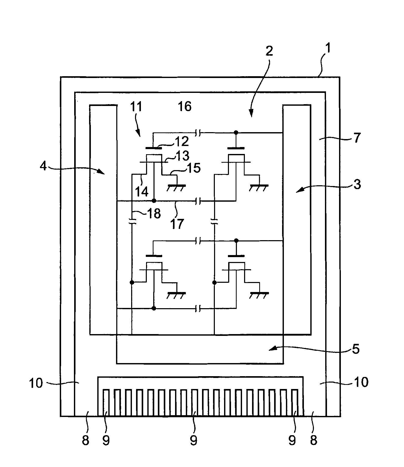
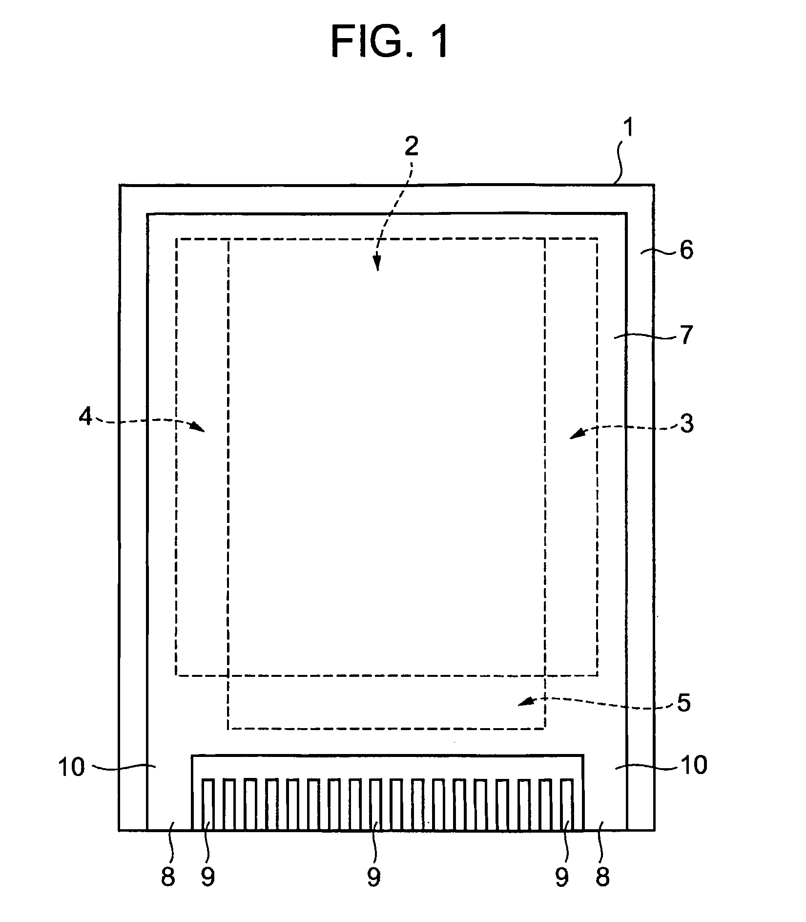
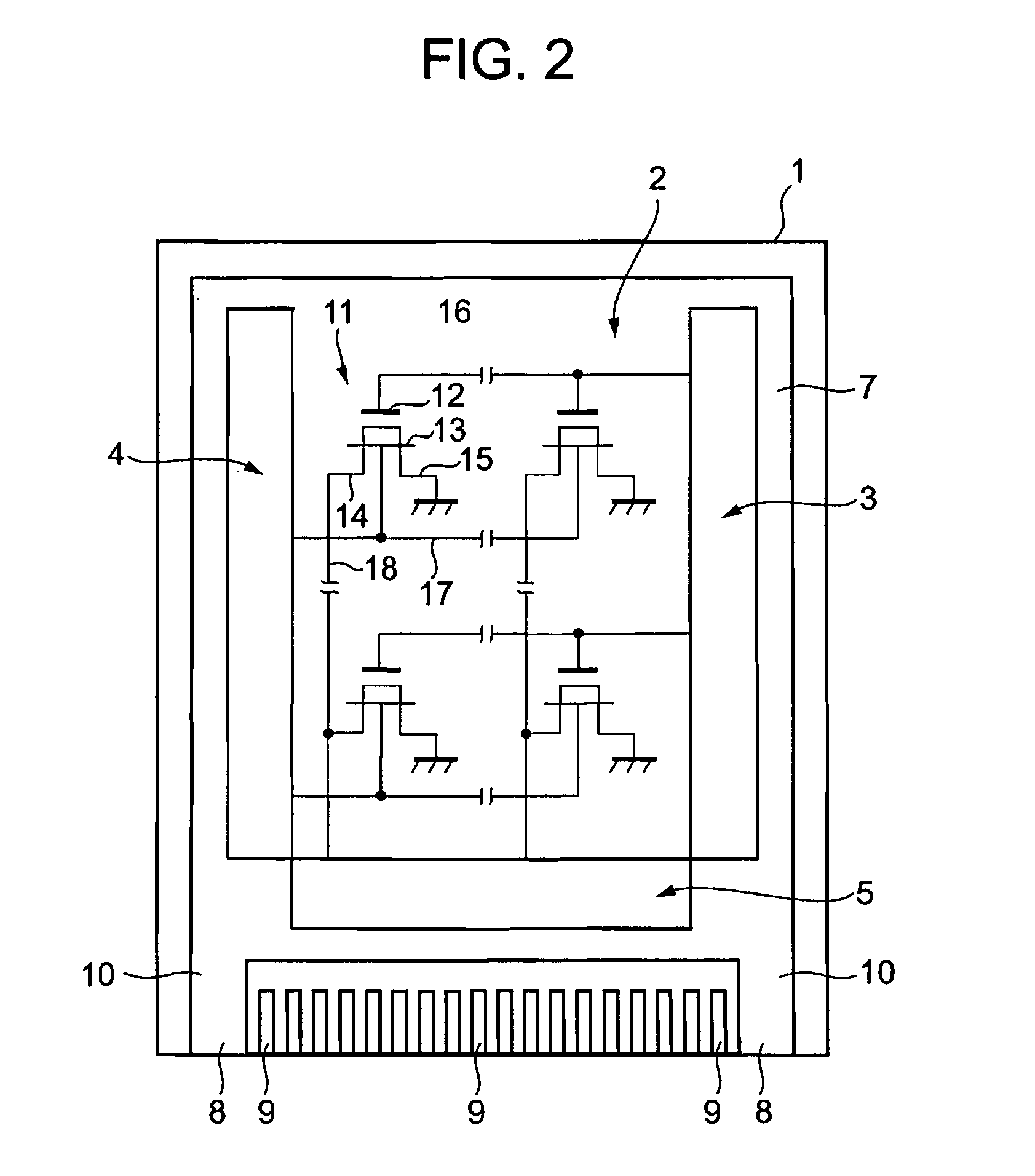
[0038]FIG. 1 is a top view diagram of the substantial part of the image reading apparatus in a first embodiment of the present invention.

[0039]This reading apparatus is comprised with a glass substrate 1. A plurality of photosensors is arranged in a matrix form (two-dimensional) substantially in the central part of a read area 2 (described later) above the glass substrate 1. A 1st, 2nd and 3rd driver circuit sections 3, 4, 5 (described later) are provided for driving a plurality of photosensors provided in the read area 2.

[0040]Above the glass substrate 1 including a plurality of photosensors provided in the read area 2 and the 1st to 3rd driver circuit sections 3, 4, 5, a transparent insulating film 6 composed of an overcoat film (described later) is provided. A transparent conductive film 7 for electrostatic protection is provided on the upper surface of the transparent insulating film 6 in the portion corresponding to an area...

second embodiment

[0072](Second Embodiment of the Image Reading Apparatus)

[0073]FIG. 4 is a top view diagram of the substantial part of the equivalent circuit of the image reading apparatus in the second embodiment of the present invention.

[0074]In this reading apparatus the difference from the case of the first embodiment as shown in FIG. 2 is that electrostatic protection elements are formed together as one unit above the glass substrate 1 between the plurality of photoelectric type thin film transistors 11 arranged in the read area 2 and for example the 2nd driver circuit section 4 (bottom gate driver).

[0075]Specifically, above the glass substrate 1 between the read area 2 and the 2nd driver circuit section 4, 1st and 2nd electrostatic protection lines 61 and 62 are provided and extended in a row direction. Diode connection type 1st and 2nd thin film transistors 63 and 64 for electrostatic protection are provided in parallel between the 1st and 2nd electrostatic protection lines 61 and 61 on eithe...

third embodiment

[0121](Third Embodiment of the Image Reading System)

[0122]FIG. 7 is a perspective diagram of the substantial part of the image reading system in the third embodiment of the present invention.

[0123]Here, with respect to any configuration equivalent to the image reading system mentioned above, the equivalent or same nomenclature is appended and further detailed explanation is abbreviated or omitted.

[0124]In this image reading apparatus the difference from the case of the first embodiment as shown in FIG. 5 is that the opposing substrate 53 of the liquid crystal display panel 51 is combined as a glass substrate (72) with the photosensor panel 71.

[0125]Specifically, a plurality of photoelectric conversion type thin film transistors 11 (not shown) are arranged in a matrix form in the external surface of the opposing substrate 53 of the liquid crystal display panel 51. Also, the read area 73, the 1st to 3rd driver circuit sections 74, 75, 76 and a plurality of external connection terminal...


PUM

PropertyMeasurementUnit
transparentaaaaaaaaaa
transparent conductiveaaaaaaaaaa
surface areaaaaaaaaaaa

Abstract

An image reading system comprising a display panel with an image display area formed by a plurality of display pixels which emits display light and displays an image in a viewing field side corresponding to a display signal from the image display area; a transparent substrate which has a read area provided in a viewing field side of the display panel; a plurality of photosensors formed in the read area above the transparent substrate; a driver circuit section formed in an outer side of the read area as one unit with the photosensors; a transparent conductive film for electrostatic protection is provided in an upper part of a plurality of photosensors and the driver circuit section; and comprises a photosensor panel which reads an image of a detectable object placed on the read area that penetrated at least some of the display light emitted from the image display area.

Description

CROSS-REFERENCE TO RELATED APPLICATIONS[0001]This application is based upon and claims the benefit of priority from the prior Japanese Patent Applications No. 2004-091190, filed Mar. 26, 2004 and No. 2004-091191, filed Mar. 26, 2004, the entire contents of which is incorporated herein by reference.BACKGROUND OF THE INVENTION[0002]1. Field of the Invention[0003]The present invention relates to an image reading apparatus and image reading system comprising the image reading apparatus. More particularly, the present invention relates to an image reading apparatus which can be suitably carried in a portable electronic device as well as favorably read a detectable object image.[0004]2. Description of the Related Art[0005]In recent years, the continuous global proliferation of Information Technology Equipment (ITE) and other compact electronic devices, such as cellular phones, Personal Digital Assistants (PDAs), etc. has been truly remarkable. Furthermore, there is a growing public demand...

Claims


Application Information

Patent Timeline
Patent Type & Authority Patents(United States)
IPC IPC(8): G06K9/00G06K5/00G06K9/74G02F1/133
CPCG06K9/00053G06K9/0004G02F1/13338G06V40/1329G06V40/1318A47K7/02D06M11/00D06M15/643
Inventor SASAKI, KAZUHIROKANBARA, MINORU
Owner ORTUS TECH
Why Eureka
Try Eureka