
Method of and system for allocating resources to resource requests

a resource request and resource allocation technology, applied in the field of data network and load balancing, can solve the problems of significant scaling and web transaction latency issues for web site administrators, reducing the response time of web sites, and increasing traffic handling capacity

Active Publication Date: 2008-01-22
RPX CORP
View PDF63 Cites 291 Cited by
  • Summary
  • Abstract
  • Description
  • Claims
  • Application Information

AI Technical Summary

Benefits of technology

[0006]A first embodiment of the invention comprises a system for allocating a resource to a service request representing a request for a category of service selected from amongst a plurality of possible categories. The system comprises first lo

Problems solved by technology

Secondly, it decreases the web site's response time and increases the traffic handling capacity by allowing multiple servers to be used together as a single web site.
Due to the complexity of this task, there have been bottlenecks due to limited CPU time and CPU memory bandwidth.
These limitations have presented significant scaling and web transaction latency issues to web site administrators.

Method used


Image

  • Method of and system for allocating resources to resource requests
  • Method of and system for allocating resources to resource requests
  • Method of and system for allocating resources to resource requests

Examples


example application

[0047]An example application of a system and method according to the invention is described in this section. This example is being provided solely to add context and aid in the understanding of the invention. Other applications are possible, so this example should not be taken as limiting.

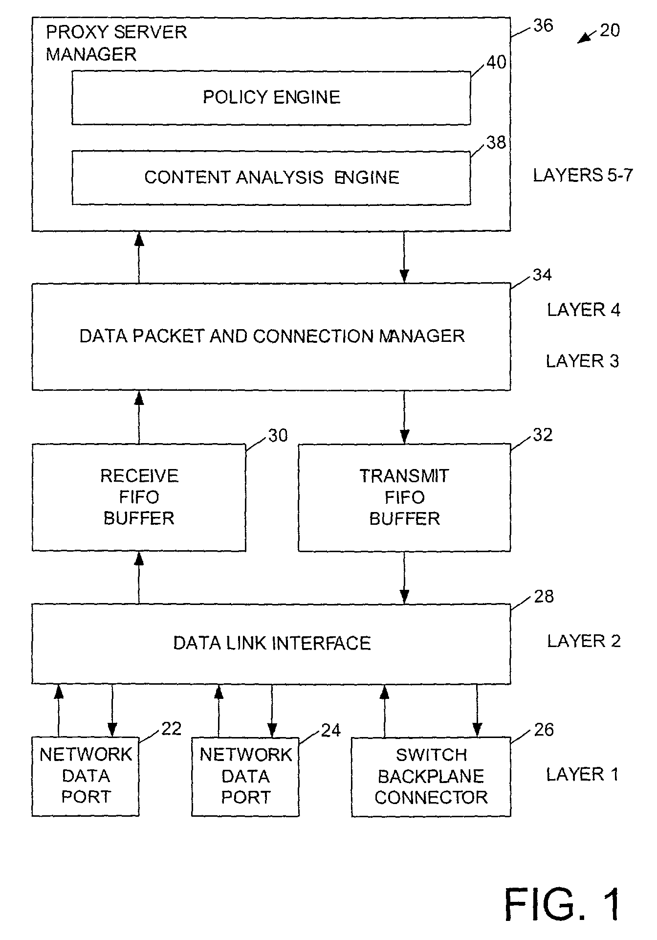
[0048]With reference to FIG. 1, there is shown a block diagram of one embodiment of a proxy server load balancer 20 incorporating the present invention. The functional blocks of the proxy server load balancer 20 are organized into various layers 1 to 5 corresponding to the Reference Model for Open Systems Interconnection (OSI) promulgated by the International Standards Organization (ISO). Layer 1 is the physical layer, layer 2 is the data link layer, layer 3 is the network layer, layer 4 is the transport layer, layer 5 is the session layer, layer 6 is the presentation layer, and layer 7 is the application layer.

[0049]The physical layer 1 includes the electrical and mechanical characteristics of the...

implementation example

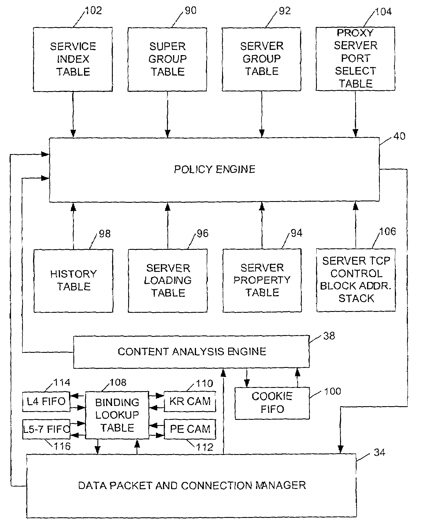
[0129]An implementation example of the foregoing useful in the example application described in the previous section will now be described. FIG. 15 shows the location and relationship in one example of the various tables in the SRAM and SDRAM introduced in FIG. 9. In one implementation, there are three SRAMs and three SDRAMs. The super group SDRAM 150 contains the service index table 102, the super group table 90, the server TCP control block address stack 106, and the proxy server port select table 104. In one implementation, the bus width for the data path is 64 bits. The base group SDRAM 154 contains the server group table 92. The bus width for the data path is also 64 bits. The server loading and property table SRAM 156 contains the server loading table 96 and the server property table 94. The history SDRAM 160 contains the history table 98. The bus width for the data path of the history SDRAM is 64 bits.

[0130]As shown in FIG. 16, the data bus for base group SDRAM 154 can be sha...


PUM


Abstract

A system and method of allocating a resource to a service request. Servers are virtually assigned through a hierarchy including groups of servers and super groups of the groups of servers. Each service request type is associated with a service index that determines both a super group and a load balancing policy for that service request type. A load balancing policy may be applied to select a group of servers among several server groups associated with the super group. Another load balancing policy is applied to the selected group of servers to select a server to handle the service request. The hierarchical data structure allows servers to be configured into overlappable, arbitrary subsets that can address service requests matching configured content rules. Load balancing policies can be selected by service request type.

Description

RELATED APPLICATIONS[0001]This application is related to U.S. Provisional Application No. 60 / 335,922, entitled “Network Switch”; U.S. patent application Ser. No. 10 / 073,483, entitled “Method Of And System For Allocating Resources To Resource Requests Based On Application Of Persistence Policies”; U.S. patent application Ser. No. 10 / 073,538, now U.S. Pat. No. 7,152,124, entitled “Method And System For Maintaining Temporal Consistency Of Resources And Data In A Multiple-Processor Packet Switch”; U.S. patent application Ser. No. 10 / 073,638, now U.S. Pat. No. 6,781,990, entitled “Method And System For Managing Traffic In A Packet Network Environment”; U.S. patent application Ser. No. 10 / 073,484, entitled “Method And System For Translating Packet Sizes In A Network”; and U.S. patent application Ser. No. 10 / 098,957, entitled “Switching System.” Each of the foregoing applications is filed concurrently herewith, and owned in common by the assignee hereof. Moreover, each of these application...

Claims


Application Information

Patent Timeline
IPC IPC(8): G06F15/177G06F9/46H04Q7/20
CPCG06F9/5033G06F9/505H04L29/12783H04L61/35H04L67/1008H04L67/1027H04L67/1034H04L67/1002H04L67/1017H04L67/1023H04L67/101G06F2209/5016G06F2209/5011H04L67/1001
Inventor ZHANG, HUIDE LA IGLESIA, ERIKGOMEZ, MIGUELLIU, LIANGLOWE, RICK K.WALLACE, MARK AARONWANG, WEI
Owner RPX CORP
Learn More