Intake duct

a technology of intake duct and intake duct, which is applied in the direction of combustion air/fuel air treatment, engine components, feed systems, etc., can solve the problems of intake noise generation, intake noise becomes noticeable, and the risk of a drawback

Active Publication Date: 2008-01-29
TOYODA GOSEI CO LTD
View PDF7 Cites 13 Cited by
  • Summary
  • Abstract
  • Description
  • Claims
  • Application Information

AI Technical Summary

Benefits of technology

[0016]In addition, in this intake duct, the divided body has in at least part of the inner peripheral edge of the opening the vertical wall portion which protrudes outwards from the duct wall of the divided body along the inner edge of the opening, and at least part of the joining portion of the air-permeable member is embedded in the vertical wall portion in such a manner as to be held therein in the thickness direction thereof. Due to this, when insert molding, the thermoplastic resin which flows into a portion of the cavity which corresponds to the vertical wall portion comes to penetrate into the outer edge of the air-permeable member from three directions; from both sides in a thickness direction and an edgewise face of the air-permeable member. Due to this, the impregnation amount of the resin can be increased by securely making the vertical wall portion extend long enough relative to the thickness of the air-permeable member, whereby the resin and the fibers in the joining portion are allowed to get entwined with each other in a more ensured fashion. In addition, since the joining portion of the air-permeable member is embedded in the vertical wall portion in such a manner as to be held therein in the thickness direction, the joining portion and the vertical wall portion is joined to each other by a mechanical connecting force. Consequently, the joining strength between the divided body and the air-permeable member can be increased in an ensured fashion.
[0017]In addition, the drawback that the outer edge of the air-permeable member is turned up can be prevented effectively in the portion where the joining portion of the air-permeable member is embedded in the vertical wall portion.
[0020]In this intake duct, the vertical wall portion is formed in pair in the long side portions of the opening which is formed into the rectangular shape, and the joining portion of the air-permeable member is embedded in the facing inner surfaces of the vertical wall portions formed in pair. Due to this, in the opening and the air-permeable member, the joining of the vertical wall portions to the joining portion can be secured over a long range of the long side portions. Consequently, the invention is advantageous in increasing the joining strength between the divided body and the air-permeable member.
[0022]In this intake duct, the drawback that the outer edge of the air-permeable member is turned up can be prevented effectively in the short side portions of the substantially rectangular shape. In addition, since the inner surface of the joining portion in the short side portions of the air-permeable member is made substantially level with the inner wall surface of the divided body, the invention is advantageous in causing air to flow smoothly within the intake passageway, thereby making it possible to suppress an increase in intake pressure loss which is attributed to the provision of the air-permeable member.
[0024]In this intake duct, since the joining portion is embedded in the frame-like vertical wall portion along the whole of the outer peripheral edge of the air-permeable member, the joining strength of the air-permeable member relative to the divided body can be increased further.
[0025]According to the intake duct of the invention, irrespective of the thickness of the divided body and the air-permeable member, the joining properties of the joining portion can be improved, and the joining properties of the air-permeable member relative to the second divided member can be made highly reliable.

Problems solved by technology

In an intake system of an automotive engine, there exists a problem that intake noise is generated from an intake duct when outside air is introduced therethrough into the engine.
This intake noise becomes noticeable in particular when the engine speed is low.
Due to this, the joining strength of the porous sheet 83 relative to the divided body 84 becomes deficient, and hence, there has been a risk of a drawback occurring that an outer edge of the porous sheet, for example, is turned up outwards.

Method used


Image

  • Intake duct
  • Intake duct
  • Intake duct

Examples


embodiment 1

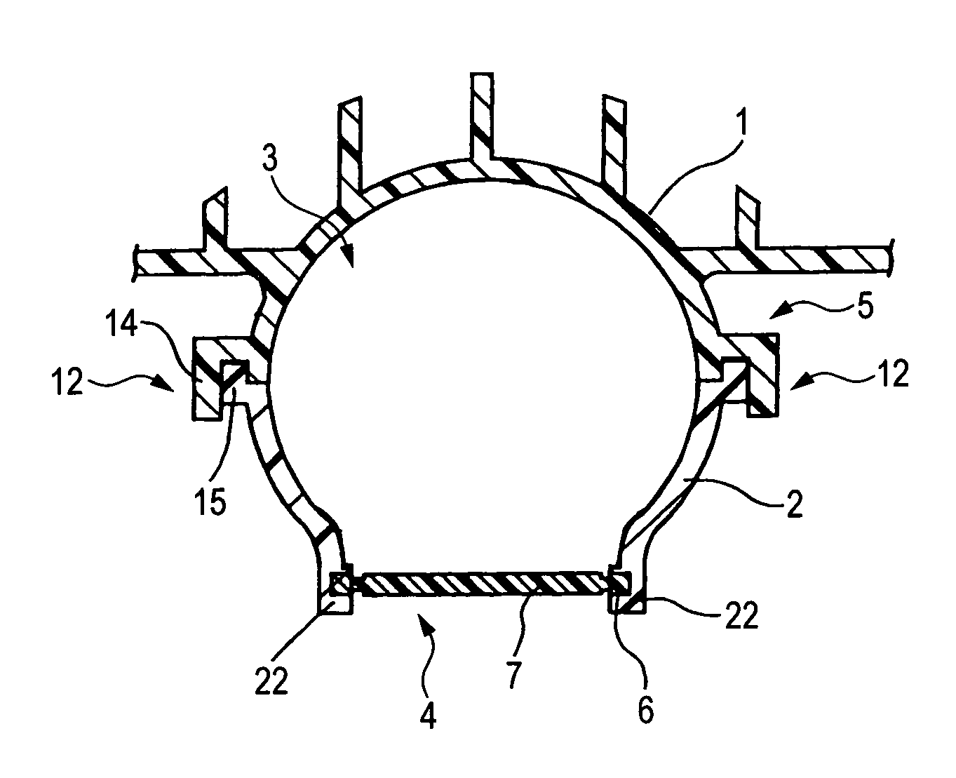
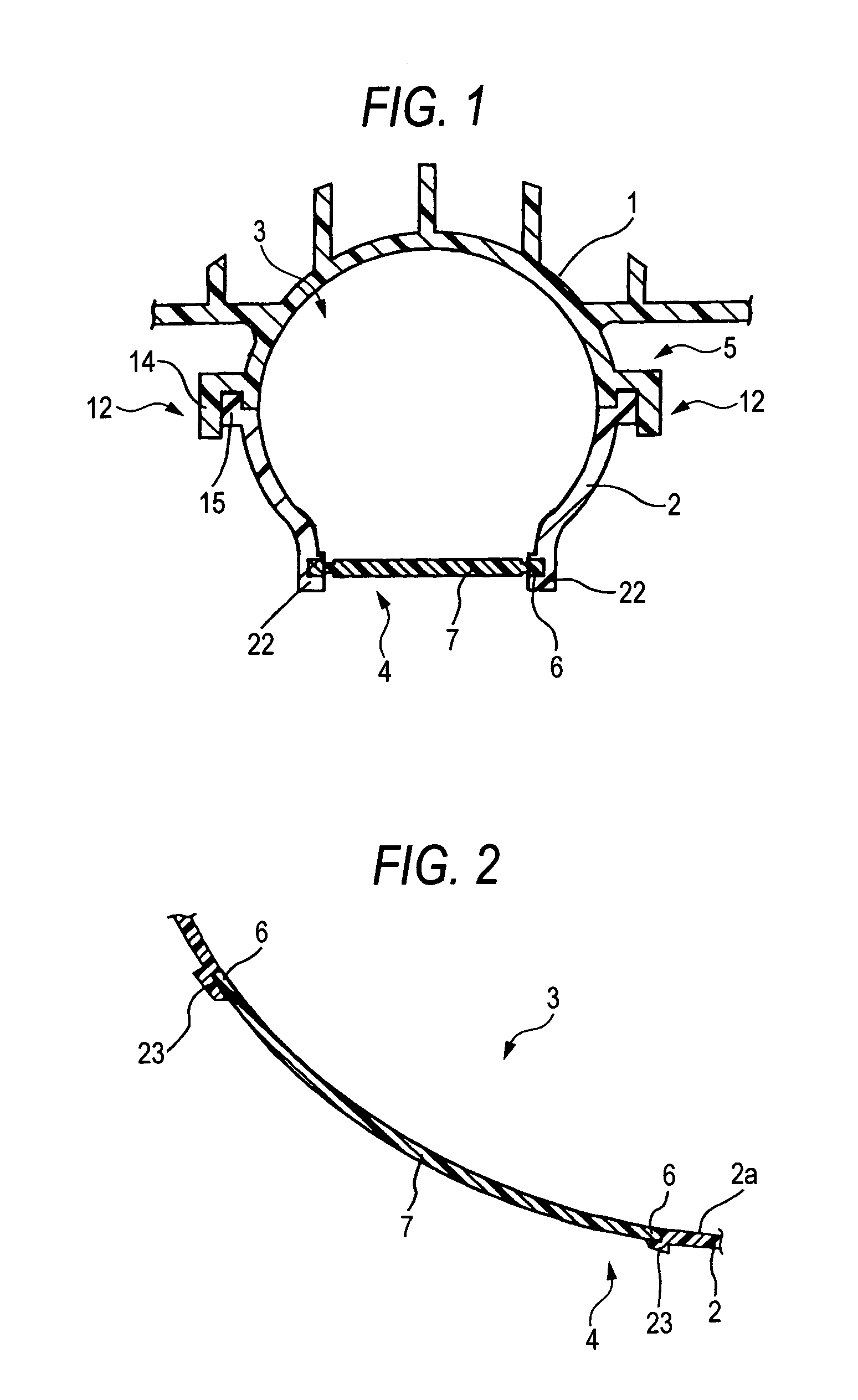
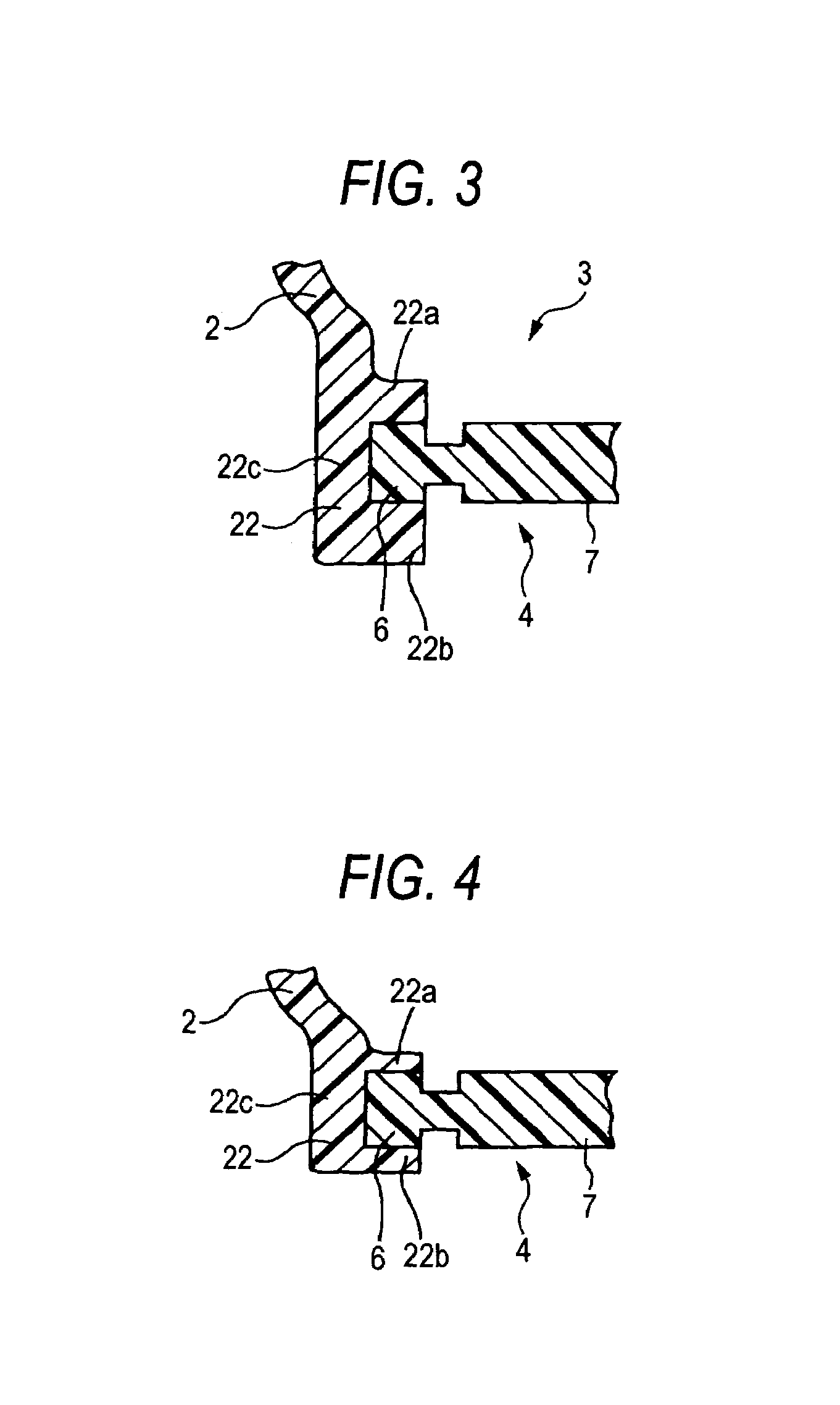
[0042]FIG. 1 is a sectional view taken along the line B-B in FIG. 6 which shows an opening and a portion where an air-permeable member is placed of an intake duct of this embodiment. FIG. 2 is a sectional view taken along the line A-A in FIG. 5 which shows the opening and the portion where the air-permeable member is placed of the intake duct. FIG. 3 is a partial sectional view taken along the line B-B in FIG. 6 which shows a main part of the intake duct in an enlarged fashion. FIG. 4 is a partial sectional view taken along the line C-C in FIG. 6 which shows the main part of the intake duct in an enlarged fashion. FIG. 5 is a front view which results when the intake duct is seen from the side of an inlet port thereof. FIG. 6 is a side view of the intake duct. FIG. 7 is a plan view of the intake duct. FIG. 8 is a sectional view taken along the line D-D in FIG. 8 which shows mainly a resonator of the intake duct. FIG. 9 is a sectional view taken along the line F-F in FIG. 7 which show...

embodiment 2

[0067]In an intake duct according to this embodiment, which is shown in FIG. 14, a second divided body 2 has along the whole of an inner peripheral edge of an opening 4 (a pair of long side portions and a pair of short side portions of the opening 4) a frame-like vertical wall portion 24 which extends along an inner edge of the opening 4 and protrudes outwards from a duct wall of the second divided body 2. This frame-like vertical wall portion 24 extends substantially at right angles to a duct axis of an intake duct 5. In addition, the frame-like vertical wall portion 24 has a height which is uniform along the full periphery thereof.

[0068]In addition, a joining portion 6 lying along the whole of an outer peripheral edge of an air-permeable member 7 (a pair of long side portions and a pair of short side portions of the air-permeable member 7) is embedded in an inner peripheral surface of the frame-like vertical wall portion.

[0069]Namely, the frame-like vertical wall portion 24 has a ...


PUM


Abstract

A duct main body is formed into a hollow tubular shape having in an interior thereof an intake passageway for introducing outside air into an internal combustion engine by connecting integrally a plurality of divided bodies such as a first divided body and a second divided body which are formed of a thermoplastic resin and has in a duct wall of the second divided body an opening which establishes a communication between the inside and outside of the intake passageway. An air-permeable member is insert molded in the second divided body in such a manner as to cover the opening. The air-permeable member has on an outer edge thereof a joining portion which is impregnated with the thermoplastic resin. The second divided body has in at least part of an inner peripheral edge of the opening a vertical wall portion which protrudes outwards from the duct wall of the second divided body along an inner edge of the opening, and at least part of the joining portion of the air-permeable member is embedded in the vertical wall portion in such a manner as to be held therein in a thickness direction.

Description

BACKGROUND OF THE INVENTION[0001]1. Field of the Invention[0002]The present invention relates to an intake duct for introducing outside air into an internal combustion engine and more particularly to an intake duct which can reduce intake noise.[0003]2. Related Art[0004]In an intake system of an automotive engine, there exists a problem that intake noise is generated from an intake duct when outside air is introduced therethrough into the engine. This intake noise becomes noticeable in particular when the engine speed is low.[0005]Then, as an intake duct which can reduce intake noise, there is known an intake duct in which an opening is provided in a duct wall of the intake duct in such a manner as to establish a communication between the inside and outside of an intake passageway, and an air-permeable member is provided in such manner as to close the opening so provided (for example, refer to JP-A-2002-106431.).[0006]As is shown in FIG. 15, this intake duct includes a duct main bod...

Claims


Application Information

Patent Timeline
Patent Type & Authority Patents(United States)
IPC IPC(8): F16L9/00
CPCF16L9/22
Inventor KINO, HITOSHIIWAO, HIROSHI
Owner TOYODA GOSEI CO LTD
Why Eureka
Try Eureka