High structural efficiency blades and devices using same

a blade and high structural efficiency technology, applied in the direction of wind energy generation, waterborne vessels, machines/engines, etc., can solve the problems of thick blades, heavy skins, porosity and delamination of thick section laminates,

Active Publication Date: 2008-01-29
GENERAL ELECTRIC CO
View PDF5 Cites 27 Cited by
  • Summary
  • Abstract
  • Description
  • Claims
  • Application Information

AI Technical Summary

Benefits of technology

[0005]It will be seen that many configurations of the present invention can reduce blade weight at tops of towers while giving the designer several ways to adjust the strength and stiffness of blades to achieve improved structural performance.

Problems solved by technology

As a result, blades have thick, heavy, skins.
If substantial care is not taken in processing, thick section laminates can be subject to porosity and delamination problems.

Method used


Image

  • High structural efficiency blades and devices using same
  • High structural efficiency blades and devices using same
  • High structural efficiency blades and devices using same

Examples


Embodiment Construction

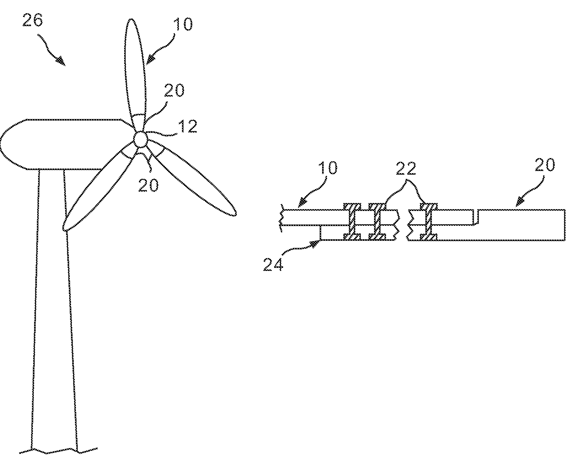
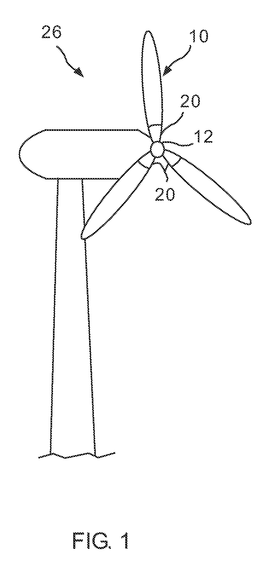
[0013]In some configurations of the present invention, integrally stiffened skin construction is used to replace prior art monolithic skin construction for wind turbine blades. Blade stiffness and structural strength are improved by geometry changes that are compatible with laminated composite material processing / fabrication. Improved structural efficiency results in reduced blade weight and material usage. When these blade configurations are used on wind turbines, a lighter weight hub results as does a lower tower weight at the top of the tower, both of which reduce structural requirements for the tower. Also provided in some configurations is a more robust, damage tolerant, attachment coupling for joining the blade to a hub.

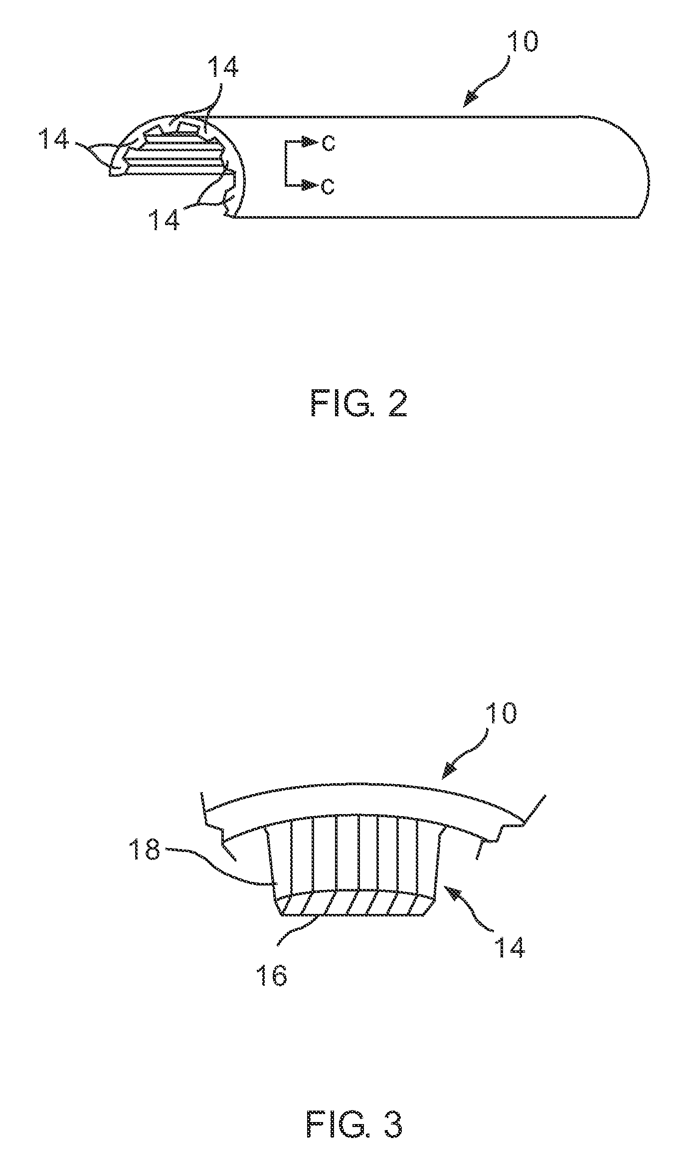
[0014]Thus, and referring to FIG. 1, some configurations of the present invention provide a blade 10 for a rotor 12. Referring to FIGS. 2 and 3, blade 10 has integral stiffeners 14 with either or both unidirectional caps 16 configured to carry blade 10 bending ...


PUM

PropertyMeasurementUnit
axial tensionaaaaaaaaaa
thicknessaaaaaaaaaa
strengthaaaaaaaaaa

Abstract

A blade for a rotor has integral stiffeners with at least one of unidirectional caps configured to carry blade bending loads in axial tension or webs to carry transverse shear resulting from blade bending.

Description

BACKGROUND OF THE INVENTION[0001]This invention relates generally to blade structure and more particularly to blade structures that offer stiffness and structural strength, and to uses of such blades. Such blades are particularly suitable for (but are not limited to use in) wind turbine configurations.[0002]Contemporary blades are made from fiberglass / epoxy composite material using monolithic, un-stiffened geometry. As a result, blades have thick, heavy, skins. If substantial care is not taken in processing, thick section laminates can be subject to porosity and delamination problems.BRIEF DESCRIPTION OF THE INVENTION[0003]One aspect of the present invention therefore provides a blade for a rotor. The blade has integral stiffeners with at least one of unidirectional caps configured to carry blade bending loads in axial tension or webs to carry transverse shear resulting from blade bending.[0004]In another aspect, the present invention provides a wind turbine having a generator, a hu...

Claims


Application Information

Patent Timeline
Patent Type & Authority Patents(United States)
IPC IPC(8): F03D11/00
CPCF03D1/0675F04D29/023F04D29/34F04D29/388F05B2260/96F05B2280/2006F05B2280/4002F05B2280/6013F05C2203/0882F05C2223/00F05C2253/16F05D2300/43F05D2300/224Y02E10/72
Inventor CAIRO, RONALD RALPH
Owner GENERAL ELECTRIC CO
Why Eureka
Try Eureka