Rapid exchange interventional devices and methods

a technology of interventional devices and catheters, applied in the field of rapid exchange interventional devices and methods, can solve the problems of destroying heart muscle tissue, difficult and time-consuming, and long guidewires

Active Publication Date: 2008-01-29
JW MEDICAL SYSTEMS LTD
View PDF38 Cites 444 Cited by
  • Summary
  • Abstract
  • Description
  • Claims
  • Application Information

AI Technical Summary

Benefits of technology

[0012]In a further aspect of the invention, the interventional device includes a collar positionable in the vascular penetration and having at least one passage therein configured to slidably receive the proximal extremity of the catheter shaft and the guidewire without substantial leakage of blood therethrough. The collar is positionable through a hemostatic device in the vascular penetration, the collar having an exterior surface configured to seal within the hemostatic device. The hemostatic device may comprise a rotating hemostasis valve (RHV) or other suitable device for introducing catheters into a vessel with minimal leakage of blood. The collar may further include a seal in communication with the at least one passage for inhibiting leakage of blood around the proximal extremity. In some embodiments, the collar comprises a first passage for receiving the catheter shaft and a second passage for receiving the guidewire tube. In other embodiments, a single passage is provided that receives both the catheter shaft and the guidewire tube.
[0018]The method may further include positioning a collar in the vascular penetration, the collar being slidably disposed over catheter shaft and the guidewire tube, wherein advancing the interventional device comprises moving the catheter shaft and guidewire tube relative to the collar. The collar may have a wire guide that extends through the slit in the guidewire tube, and wherein moving the guidewire tube relative to the collar guides the guidewire into or out of the guidewire tube. Usually, a hemostasis device is placed in the vascular penetration, and the collar is positioned in the hemostasis device. The hemostasis device provides a hemostatic seal between the hemostasis device and the collar. The interventional device may also include a seal in the collar to inhibit blood leakage from the vessel around the catheter shaft and guidewire tube.
[0019]In another aspect of the method, the guidewire tube is collapsible from an extended length to a collapsed length, wherein the guidewire tube has the collapsed length before the interventional device is inserted into the vessel and has the extended length when the interventional element is at the treatment site. The interventional device may include a collar slidable relative to the catheter shaft and coupled to the guidewire tube. In this way, advancing the interventional device relative to the collar extends the length of the guidewire tube.

Problems solved by technology

As new miniaturized and less-invasive technologies are developed, the challenge becomes one of gaining access to the anatomical regions that could benefit from new forms of diagnosis and treatment.
If the heart muscle is deprived of blood, a myocardial infarction results, destroying heart muscle tissue and potentially leading to death.
The disadvantage of such designs is that the guidewire must be very long in order to extend entirely through the catheter while the distal end of the guidewire remains positioned at the target lesion.
Further, the process of exchanging catheters (withdrawing a first catheter from the guidewire and replacing it with a second catheter) is challenging and time-consuming with over-the-wire designs because in the region of the vascular penetration, the guidewire is covered by the catheter being withdrawn until the catheter has been completely removed from the patient, preventing the physician from keeping hold of the guidewire and requiring the use of an assistant to hold the proximal end of the guidewire some distance from the patient.
While rapid exchange catheters have many advantages over over-the-wire designs, current rapid exchange catheters suffer from certain drawbacks.

Method used


Image

  • Rapid exchange interventional devices and methods
  • Rapid exchange interventional devices and methods
  • Rapid exchange interventional devices and methods

Examples


first embodiment

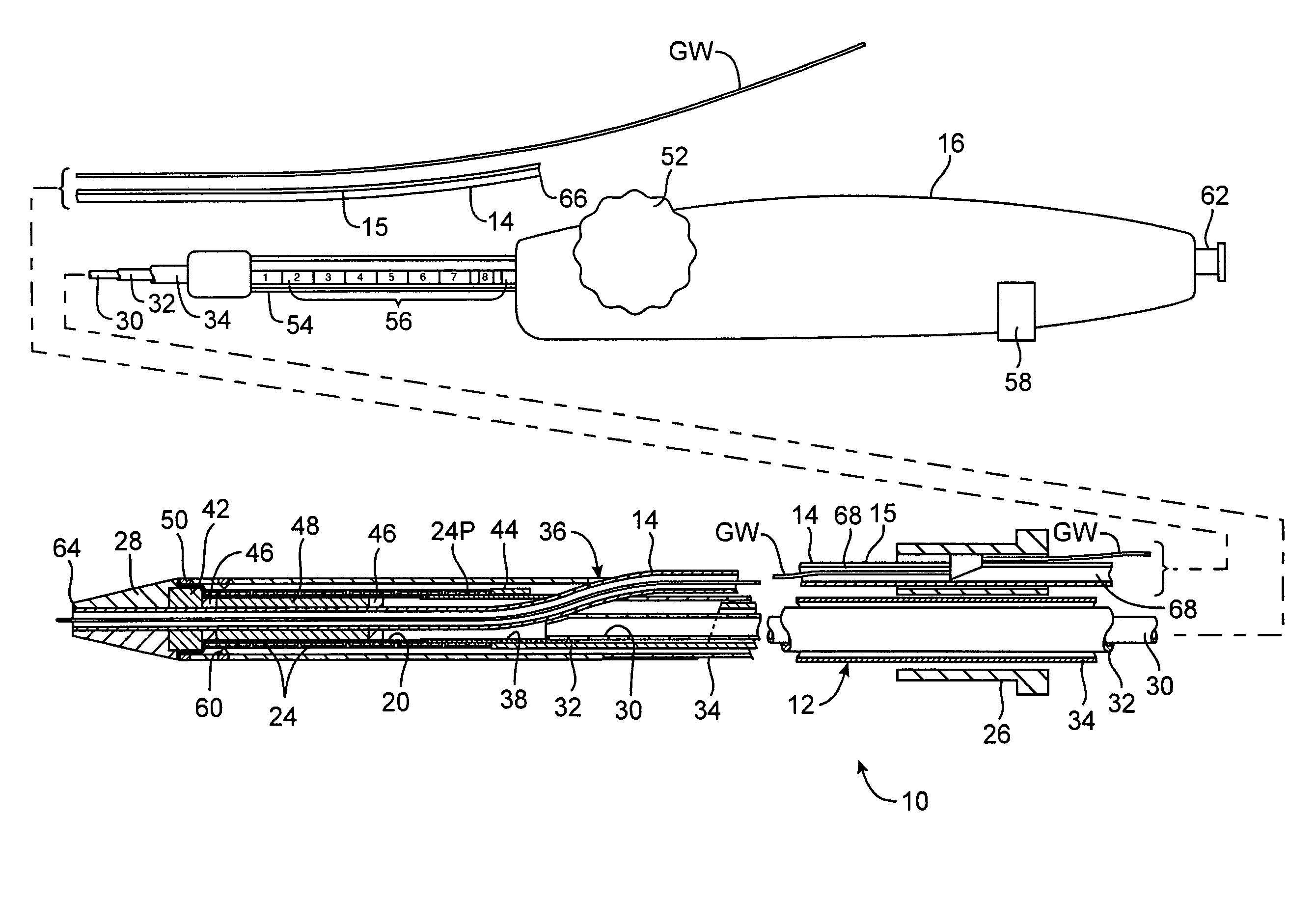
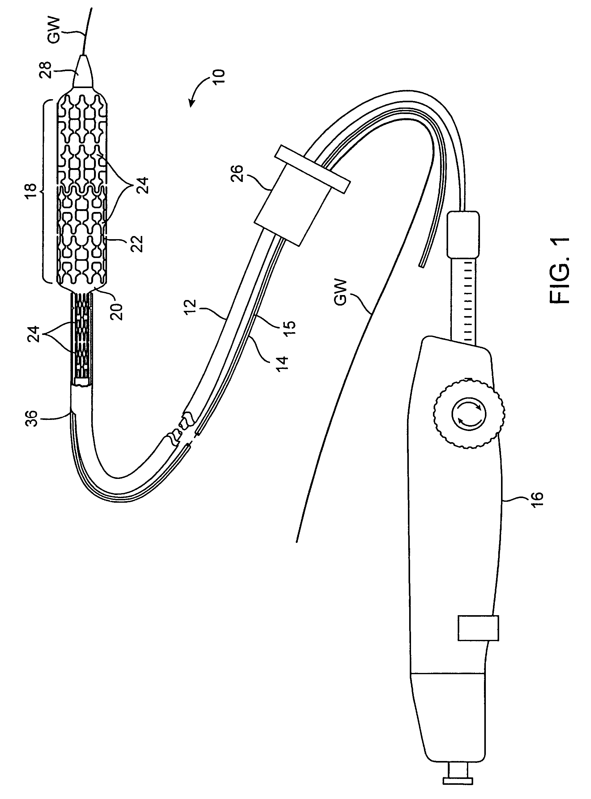
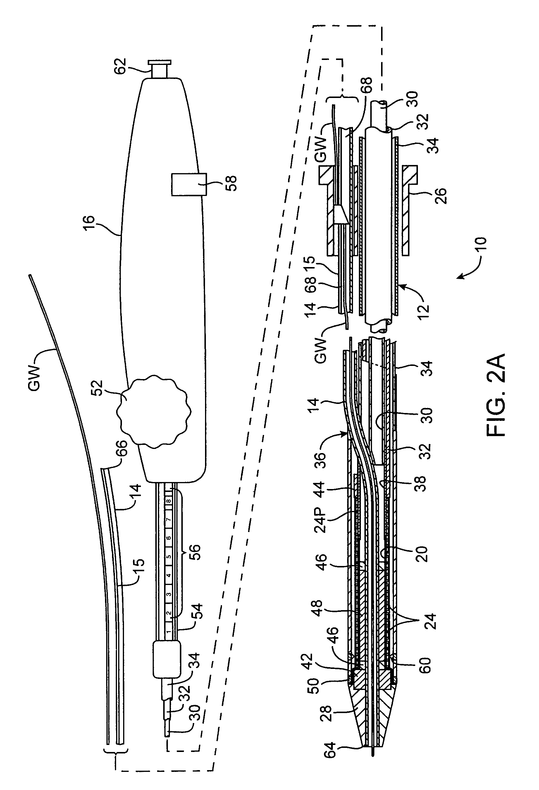
[0037]Referring to FIG. 1, an interventional device according to the invention will be described. In this embodiment, the interventional device is a stent delivery catheter 10 having a catheter body 12, a guidewire tube 14 with a longitudinal slit 15, a handle 16, and an interventional element 18. Interventional element 18 comprises an expandable balloon 20 coupled to catheter body 12, and one or more stents 22 positioned over balloon 20 for expansion therewith. In a preferred embodiment, each stent 22 comprises a plurality of separate or separable stent segments 24, some of which are shown expanded on balloon 20 while others are retained within catheter body 12. Catheter body 12 and guidewire tube 14 extend through a collar 26 and are slidable relative thereto. A guidewire GW extends slidably through guidewire tube 14 between a nosecone 28 at the distal end of catheter body 12 and collar 26.

[0038]Delivery catheter 10 has dimensions suitable for use in the anatomical region to be tr...

second embodiment

[0046]a wire guide 80A in collar 26 is illustrated in FIGS. 4A-4C. Wire guide 80A includes a generally cylindrical bottom tube 90 configured to slide within guidewire lumen 68. Bottom tube 90 may be round, oval, elliptical, disk-shaped or other suitable shape in cross-section, and may have a pointed, conical, bullet-shaped, or rounded leading edge to assist in tracking through guidewire lumen 68. Bottom tube 90 is fixed to a base 92 attached to the wall 94 of collar 26. Base 92 is configured to extend through slit 15 in guidewire tube 14. The leading edge 96 of base 92 may be tapered, peaked, rounded or have other suitable shape to assist in sliding through and spreading slit 15. A passage 98 extends from a distal opening 100 in bottom tube 90 to a proximal opening 102 on the proximal side of base 92. Distal opening is aligned with guidewire lumen 68, while proximal opening 102 is radially offset therefrom so that guidewire GW is guided from being within guidewire lumen 68 distally ...


PUM


Abstract

Wire-guided interventional devices and methods are provided which enable faster and easier catheter exchanges. The interventional devices include a catheter shaft and a guidewire tube wherein the catheter shaft and the guidewire tube each have a length sufficient to extend to the vascular penetration when the interventional device is positioned at the treatment site. In some embodiments, a collar is disposed around the catheter shaft and guidewire tube that automatically inserts or removes the guidewire from the guidewire tube or automatically collapses or extends the guidewire tube as the catheter is introduced or withdrawn.

Description

BACKGROUND OF THE INVENTION[0001]The use of wire-guided catheter interventions for diagnosis and treatment of disease is increasing dramatically. Such interventions are employed in the arterial and venous vasculature, in the heart, kidneys, liver, and other organs, in the stomach, intestines, and urinary tract, in the trachea and lungs, in the uterus, ovaries and fallopian tubes, and elsewhere. As new miniaturized and less-invasive technologies are developed, the challenge becomes one of gaining access to the anatomical regions that could benefit from new forms of diagnosis and treatment. Wire-guided catheters provide a proven, minimally-invasive approach to reaching remote regions of the body and performing diagnostic and treatment procedures with precision, safety, and reliability.[0002]A particularly well-known use of wire-guided catheters is for the treatment of coronary artery disease. In coronary artery disease, one or more coronary arteries becomes partially or fully occluded...

Claims


Application Information

Patent Timeline
Patent Type & Authority Patents(United States)
IPC IPC(8): A61F2/06A61F2/84A61M25/01A61M25/10A61M29/00
CPCA61F2/958A61M25/0169A61M25/10A61M2025/0183
Inventor ANDREAS, BERNARDGRAINGER, JEFFRY J.
Owner JW MEDICAL SYSTEMS LTD
Why Eureka
Try Eureka