Photo-sensitive MEMS structure

a technology of photo-sensitive mems and structure, applied in the field of micro-electromechanical systems, can solve the problems of damaging the structure of conventional light detectors that incorporate a photo-sensitive mems structure, intense illumination,

Inactive Publication Date: 2008-01-29
LUCENT TECH INC
View PDF12 Cites 20 Cited by
  • Summary
  • Abstract
  • Description
  • Claims
  • Application Information

AI Technical Summary

Problems solved by technology

Some conventional light detectors that incorporate a photo-sensitive MEMS structure are damaged by intense illumination.
When brought into physical contact, the two portions may permanently stick thereby damaging the MEMS structure.

Method used


Image

  • Photo-sensitive MEMS structure
  • Photo-sensitive MEMS structure
  • Photo-sensitive MEMS structure

Examples


Embodiment Construction

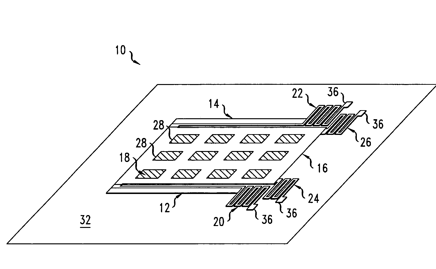
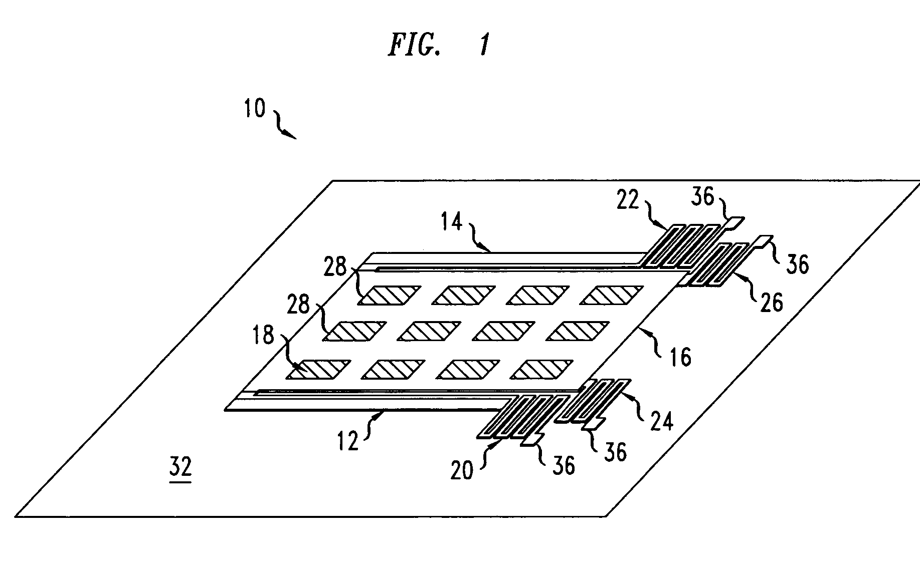
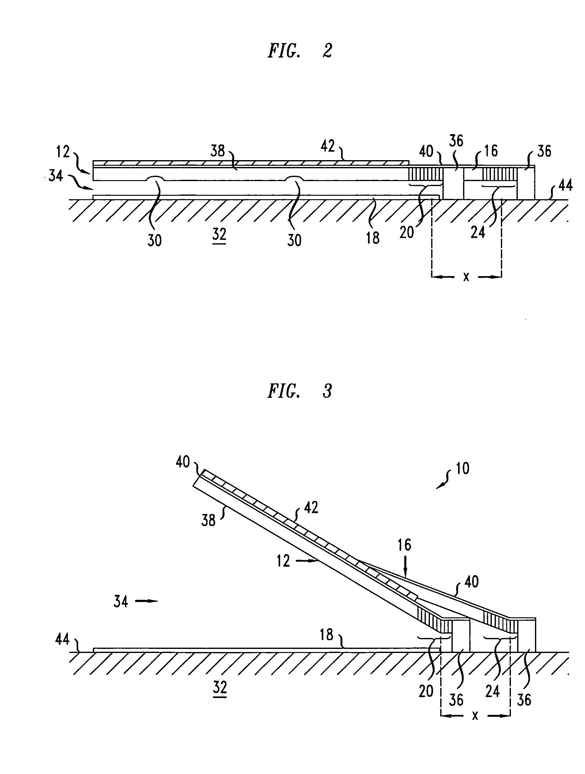
[0018]FIGS. 1-3 show a light-sensitive and / or heat-sensitive planar MEMS structure 10 that includes flexible planar arms 12, 14; mobile top plate 16; fixed bottom plate 18 visible through holes 18 in the mobile top plate 16; first planar hinges 20, 22; and second planar hinges 24, 26. Each arm 12, 14 has a first end that rigidly connects to one side of an associated first planar hinge 20, 22 and a second side that substantially rigidly connects to one side of the mobile top plate 16. One side of the mobile top plate 16 also rigidly connects to one side of the second planar hinges 24, 26. The mobile top plate 16 typically includes an array of through holes 28 and may have dimples 30 on its lower surface to aid in manufacture. The fixed bottom plate 18 is rigidly fixed to a planar surface of the substrate 32 and faces the mobile top plate 16. The substrate 32 may be a dielectric coated silicon wafer that includes CMOS control and measurement circuitry, i.e., located below the dielectr...


PUM


Abstract

A heat-sensitive apparatus includes a substrate with a top surface, one or more bars being rotatably joined to the surface and having bimorph portions, and a plate rotatably joined to the surface and substantially rigidly joined to the one or more bars. Each bimorph portion bends in response to being heated. The one or more bars and the plate are configured to cause the plate to move farther away from the top surface in response to the one or more bimorph portions being heated.

Description

BACKGROUND[0001]1. Field of the Invention[0002]The invention relates to micro-electromechanical systems (MEMS's) and light or heat sensitive detectors.[0003]2. Discussion of the Related Art[0004]Some infrared light detectors use MEMS structures. One such light detector includes a MEMS structure with a capacitor and a cantilever arm. The capacitor has a fixed plate and a mobile plate. Each cantilever arm has a first end, which is physical fixed to a substrate, and a second end, which is fixed to the mobile capacitor plate. Each cantilever arm also includes a bimorph portion that bends in response to being heated by absorption of infrared light. Bending of the bimorph portion displaces the mobile plate in a manner that changes the distance between the mobile and fixed plates of the associated absorber. Thus, illumination of one of the MEMS structures by infrared light produces a measurable change in an electrical property of the structure, i.e., the capacitance of the capacitor. By me...

Claims


Application Information

Patent Timeline
Patent Type & Authority Patents(United States)
IPC IPC(8): H01G5/00
CPCG01J5/40H02N10/00B81B2201/0292
Inventor AKSYUK, VLADIMIR ANATOLYEVICHSIMON, MARIA ELINASLUSHER, RICHART ELLIOTT
Owner LUCENT TECH INC
Why Eureka
Try Eureka